Tutorial: Connect Xiaomi LDS02RR LiDAR to Raspberry Pi (Python)
Read distance data from the ~$15 Xiaomi LDS02RR on a Raspberry Pi in Python — and run the PID + PWM loop that spins its motor at 5 Hz, which the LDS02RR cannot do for itself.

The Xiaomi LDS02RR is one of the cheapest way into 2D LiDAR — the laser distance sensor pulled from Xiaomi/Roborock robot vacuums. But it is also the most hands-on, because unlike the LDROBOT LD14P it has no onboard motor controller and no command input. It only spins, and only streams data, while you keep it turning at the right speed. This guide does exactly that on a Raspberry Pi, in Python.
All functionality in this article is now available as a Python
lds2dlibrary.
The trick: the LDS02RR must rotate at about 5 Hz (300 RPM) or it stops reporting distances. The Maker’s Pet adapter exposes a
MOT_ENPWM input; the Pi runs a PID loop that reads the speed the LiDAR reports and trims that PWM to hold 5 Hz. The packet format and PID constants are ported from the open-source kaiaai/LDS library. Tested on a Raspberry Pi 5 with software PWM on GPIO18 (the hardware-PWM path is supported but not yet verified). Tuning may vary with your setup — bug reports welcome on our support forum.
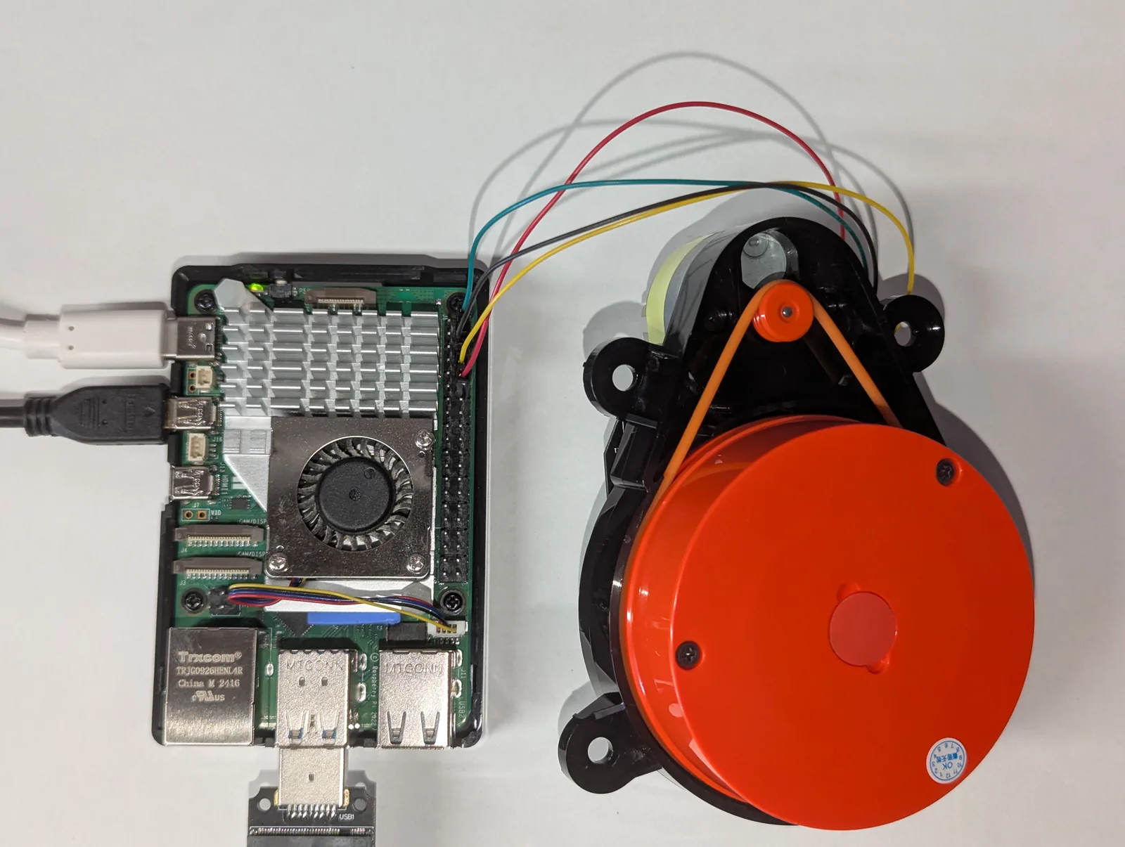
Most LiDARs we have covered manage their own motor: you power them up and they hold their speed. The LDS02RR does not. The adapter’s 4-pin connector brings out just four signals — the LiDAR’s serial TX, a MOT_EN motor-enable line, GND, and 5V. Drive MOT_EN high and the motor runs; drive it with a PWM signal and the duty cycle sets the motor voltage, and therefore the speed. There is no “set 5 Hz” command — closing that loop is your job, and that is the interesting part of this build.
Why the LDS02RR needs the host to spin it
Already connected an LDS02RR to an ESP32? That is the companion guide; here we move the same idea to a Raspberry Pi 5 and Python.
What you need
- Xiaomi LDS02RR LiDAR
- Maker’s Pet LDS02RR adapter v0.4 (ships with the JST GH cable)
- A Raspberry Pi 4 or Pi 5 on Raspberry Pi OS (Bookworm or newer)
- A strong 5V Pi power supply — the LiDAR motor pulls up to ~1A peak
Get new tutorials by email
Wiring
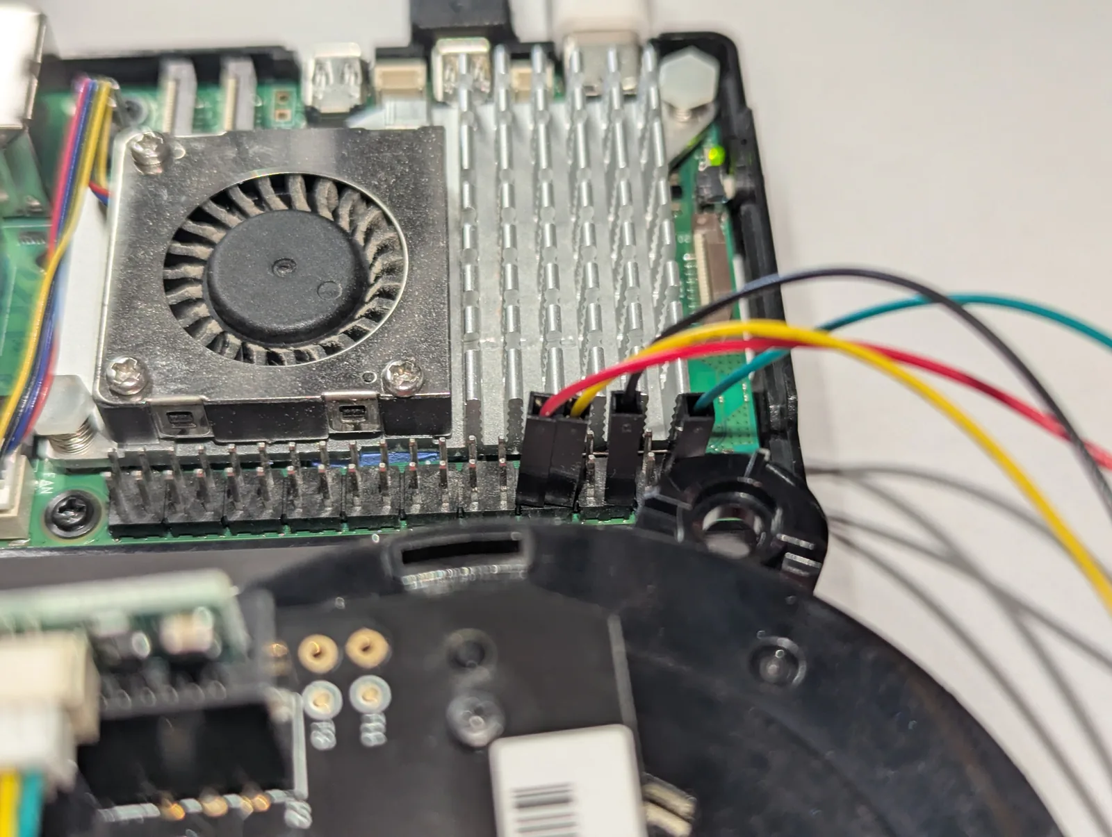
The LiDAR only talks (there is no RX to wire); the Pi listens on its serial RX and drives the motor on a PWM pin.
| Adapter pin | Pi GPIO | Board pin | Purpose |
|---|---|---|---|
| TX | GPIO15 / RXD | pin 10 | LiDAR data in (3.3V) |
| MOT_EN | a PWM GPIO | see below | motor PWM out (3.3V, several kHz) |
| GND | GND | pin 6 | common ground |
| 5V | 5 V | pin 2 or 4 | LiDAR power (~1A peak) |
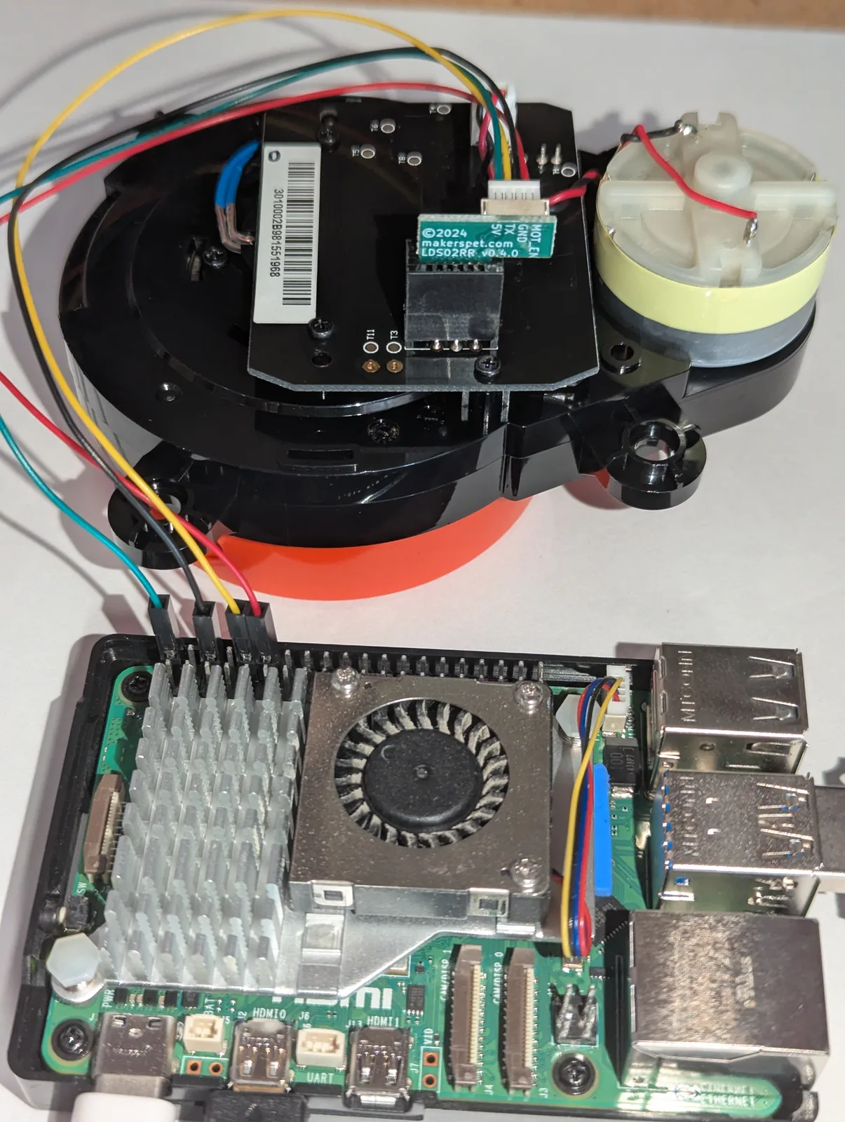
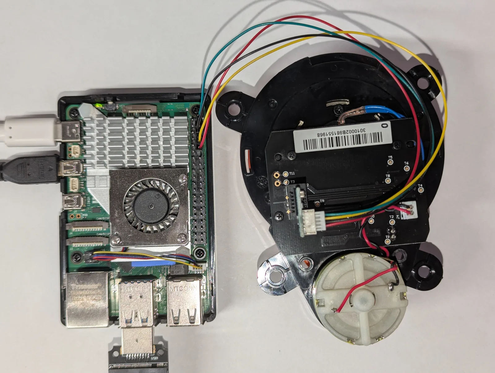
3.3V logic throughout, so no level shifter is needed.
One-time Raspberry Pi setup
Serial port: enable the GPIO UART and free it from the serial console exactly as in Part 1 of the LD14P series — the steps are identical, only the baud rate differs. The LDS02RR runs at 115200 baud.
Pick how to drive MOT_EN. You have two options, and the code supports both with a --pwm flag:
- Hardware PWM (not yet tested) — in principle cleaner, jitter-free multi-kHz, and the code supports it via
--pwm hardware. Adddtoverlay=pwm-2chanto/boot/firmware/config.txtand reboot; channels map to specific GPIOs (commonly GPIO12/13 on the Pi 5) and you may need--pwm-chip 2. We have not verified this path on hardware yet, so it is one to revisit. - Software PWM (tested) — no config change, works on any GPIO via
gpiozero. This is the path verified for this guide: on a Raspberry Pi 5 the PID held the LDS02RR at ~5 Hz over software PWM on GPIO18 (header pin 12), streaming clean data. There is some timing jitter, but the motor’s inertia smooths it out, and it is the quickest way to a first spin.
# pyserial for the data, gpiozero + rpi-hardware-pwm for the motor PWM
sudo apt install python3-serial
pip install gpiozero rpi-hardware-pwm
How the speed-control loop works
Every data packet the LDS02RR sends includes its current motor speed (RPM = the two speed bytes divided by 64). That is the feedback signal. A textbook PID compares it against the 300 RPM setpoint and nudges the MOT_EN duty cycle up or down. The PID output range is simply 0.0 to 1.0 — the duty cycle itself:
# 300 RPM = 5 Hz. The PID's output IS the MOT_EN duty cycle (0.0 - 1.0).
pid = PID(kp=3e-3, ki=1e-3, kd=0.0, setpoint=300,
          out_min=0.0, out_max=1.0, sample_ms=20)
pid.initialize(current_input=0.0, current_output=0.5)
pwm.set_duty(0.5)                       # start MOT_EN at 50%

while True:
    for packet in read_packets(serial):
        rpm, points = parse_packet(packet)   # rpm comes from the LiDAR itself
        measured_rpm = rpm
    duty = pid.compute(measured_rpm)         # runs every 20 ms
    if duty is not None:
        pwm.set_duty(duty)                   # trim MOT_EN to hold 5 Hz
At startup the motor is stationary and sends no data, so the controller ramps the duty up until the puck reaches speed and packets start arriving; then it settles onto 5 Hz. The constants (Kp=3e-3, Ki=1e-3, Kd=0, 20 ms sample) come straight from the kaiaai/LDS library that drives this same LiDAR family on microcontrollers.
How LiDARs are used in self-driving robots?
Build a real LiDAR self-driving Arduino/ROS2 robot using our kit - with complete step-by-step instructions. No robotics experience necessary.
See the full robot kit →Reading the data packets
The LDS02RR uses the well-documented Neato XV11 format: 22-byte packets, four distance readings each, 90 packets per revolution for a full 360°. Each reading carries a distance, a signal-quality value, and two flag bits that mark unreliable points. A word-sum checksum guards every packet.
COMMAND = 0xFA            # 22-byte packet: start, index, speed, 4 points, checksum
def parse_packet(pkt):
    start_angle = (pkt[1] - 0xA0) * 4        # 90 packets * 4 points = 360 degrees
    rpm = (pkt[2] | (pkt[3] << 8)) / 64.0    # motor speed, fed back to the PID
    ...                                      # 4 distance/quality readings follow
The full parser, PID, and PWM back ends live in one readable file, lds02rr_pi.py.
Run it
# tested path: software PWM on GPIO18 (header pin 12), summarized output
python3 lds02rr_pi.py --pwm software --pwm-pin 18

# one line per measurement point
python3 lds02rr_pi.py --pwm software --pwm-pin 18 --raw

# watch only the spin-up and speed lock (handy for tuning)
python3 lds02rr_pi.py --pwm software --pwm-pin 18 --spin

# hardware PWM (not yet tested; see the setup note above)
python3 lds02rr_pi.py --pwm hardware
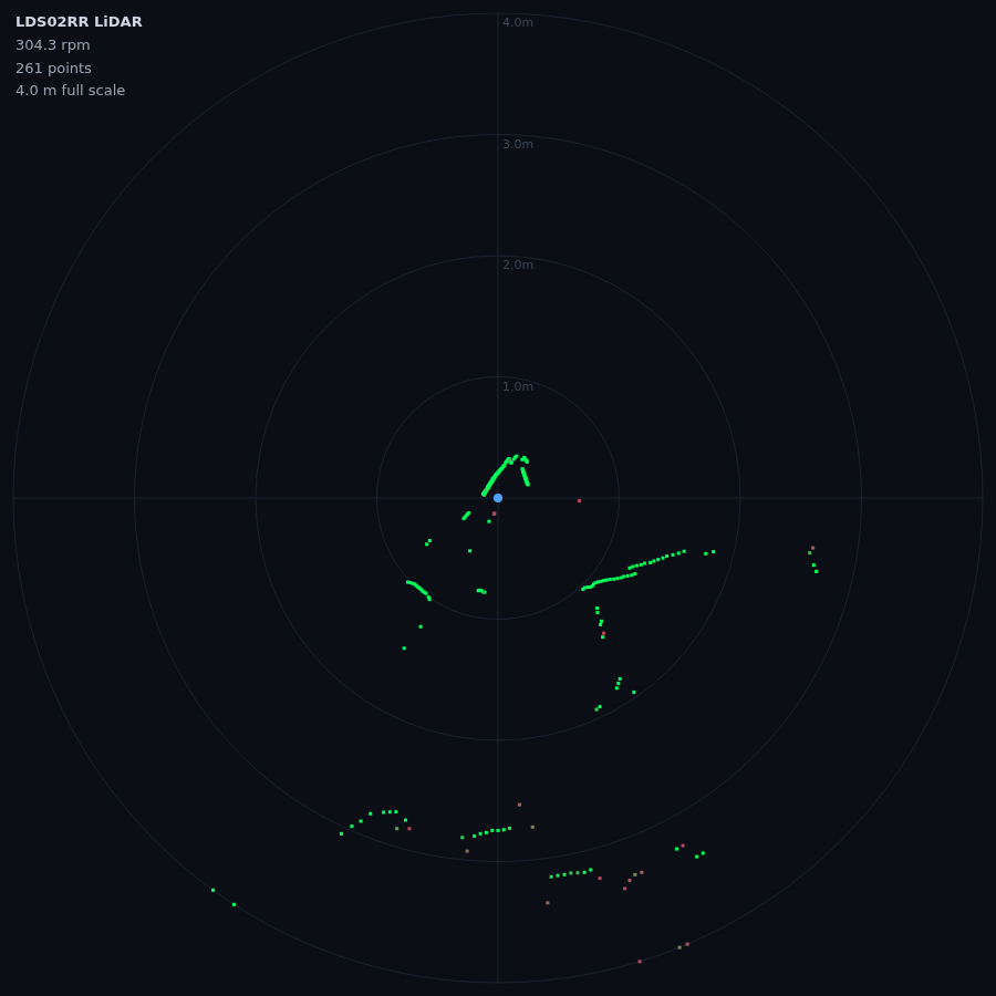
Power up, start the script, and watch the spin-up: the duty cycle climbs, the puck comes up to speed, and once it is near 5 Hz the distance lines start scrolling. --spin shows just the live RPM and duty so you can confirm the loop locks before you worry about the data. The motor is stopped automatically when you press Ctrl-C.
If it will not hold speed
- Make sure your 5V supply has headroom — a sagging rail starves the motor.
- Prefer hardware PWM; heavy CPU load can make software PWM jitter enough to disturb the loop.
- Re-tune with
--kp,--ki,--kd, and watch the response with--spin.
Where this is going
Once the LDS02RR holds 5 Hz and streams clean distances, it feeds the same pipeline as any other LiDAR: a live browser radar, obstacle detection, and — published as a ROS 2 LaserScan — SLAM and Nav2 mapping.
Parts used here: the Xiaomi LDS02RR LiDAR and the LDS02RR adapter v0.4. All the code is in the rpi5_lds02rr repository under the Apache 2.0 license.