How OOMWOO cleaning algorithms work
Here are issues we've ran into building OOMWOO open-source vacuum's cleaning, mapping and navigation - and our solutions.

OOMWOO is our open-source, ROS 2, 3D-printable robot vacuum. Here are issues we’ve ran into building its cleaning, mapping and navigation – and our solutions.
Stuck Robot
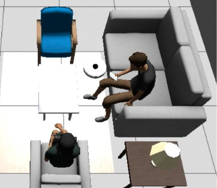
In simulation the vacuum cleaned open floor just fine – but the moment it approached a wall or the front of the sofa, it would stop and grind in place, replanning over and over, sometimes looping for fifteen minutes. It looked hopelessly stuck. It turned out it wasn’t stuck at all. This is the story of a bug that was easy to misread by eye and obvious the moment we measured it – and the two-part fix that roughly doubled coverage near obstacles.
The symptom
Watching a run, the robot would drive toward furniture, slow down, and then wedge – working its wheels, cancelling and re-issuing navigation goals, burning minutes without making progress. Every instinct said it was physically trapped against the sofa and needed a better escape maneuver.
Diagnosis: measure, don’t guess
Instead of designing an escape behavior on a hunch, we instrumented a stall and logged what was actually happening. Two numbers settled it:
- 0 bumper contacts during the entire stall – the robot was never physically touching anything.
- ~90 “collision ahead” aborts from the controller in the same window.
That combination is decisive. The navigation controller (Nav2’s Regulated Pure Pursuit) was aborting on a predicted collision that never physically happened. Its forward collision check projects the robot’s footprint ahead and refuses to enter cells marked lethal on the costmap. Because our obstacle inflation is tuned tight (more on that below), the robot halted about six centimetres before its body would have touched – close enough to look stuck, far enough that the bumper never fired. A phantom obstacle.
Why the costmap is deliberately tight
The robot’s inscribed radius is 0.1745 m. The obstacle-inflation radius is a trade-off, and for a vacuum it wants to be small:
- Inflate at or above ~0.175 m and every gap narrower than about twice that gets sealed off – the robot never threads between furniture legs, so it never cleans there.
- Inflate down near 0.02 m and the controller can’t find valid trajectories at all.
- At 0.10 m it threads the gaps nicely – but grazes obstacles, which is exactly what exposed the phantom.
A vacuum genuinely wants to run tight to walls and furniture – that’s the whole job. So the tight inflation is correct. What’s wrong for this robot is the collision-averse controller behavior on top of it.
The fix, in two parts
The two parts are gated: the first has to happen for the second to do anything, because until the robot actually reaches contact there’s nothing for a bumper-driven behavior to react to.
1. Let the robot reach contact
Turn off the controller’s forward collision check. A vacuum is contact-tolerant: it has a bumper and is meant to touch things. Let it drive right up to walls and furniture, and let the bumper own near-obstacle safety.
# nav2_params.yaml (RegulatedPurePursuitController)
use_collision_detection: false   # was: true
The effect was immediate: collision aborts dropped to zero, and the bumpers started firing – the robot was finally reaching the obstacles it had been hovering in front of.
2. Peel off the held bumper
Reaching contact is only useful if the robot then reacts well. We added a small reactive behavior to the coverage planner, layered under the coverage goals. When a bumper stays pressed continuously for about 1.5 seconds, the planner:
- cancels the active navigation goal immediately, instead of waiting for Nav2 to give up while the robot leans on the obstacle;
- turns away from the pressed side – left bumper held, rotate right; right bumper held, rotate left – rather than a blind straight reverse;
- records a no-go pocket so the coverage sweep doesn’t immediately route straight back in;
- backs and peels for a moment, then hands control back to Nav2.
This is the classic robot-vacuum “bumper held, panic turn” reflex, keyed on which bumper is pressed rather than on the costmap.
Results
Measured on the same living-room world over a fixed 135-second window:
| Configuration | Coverage | Collision aborts | Physical contact |
|---|---|---|---|
| Baseline (stock Nav2) | ~20% | ~90–105 | never touches (phantom) |
| Combined fix | ~36% | 0 | reaches contact, peels off cleanly |
To be clear: ~36% coverage in a 135-second window is not consumer-vacuum performance – this is early simulation work, on one world, and there’s plenty left to tune. The point isn’t the absolute number. It’s that the robot now cleans near obstacles instead of grinding against phantom ones, the improvement is repeatable, and the approach is the right shape to build on.
Why a vacuum should be allowed to touch things
Real robot vacuums don’t escape near-obstacle situations with navigation-stack recoveries. Nav2’s built-in spin and backup recoveries are collision-averse – they check the costmap and refuse to move into the very cells the robot is wedged against, so they stall exactly when you need them. A vacuum has a bumper and is supposed to make contact. The right architecture is a small reactive, bumper-driven behavior layer that runs open-loop, ignores the costmap, and overrides the planner while in contact. Coverage plans the open floor; this reflex handles the last few centimetres. (Anyone who has read iRobot’s coverage patents will recognize the pattern: the escape logic keys on the bumper, not the map.)
Try it yourself
Everything here runs headless in the OOMWOO dev container. Run it with GUI – no robot needed:
docker pull makerspet/oomwoo:jazzy-dev
docker run -d --name oomwoo makerspet/oomwoo:jazzy-dev sleep infinity
docker exec -it oomwoo bash

# inside the container:
GZ=$(ros2 pkg prefix oomwoo_gazebo)/share/oomwoo_gazebo
SIM=$(ros2 pkg prefix oomwoo_sim_support)/share/oomwoo_sim_support

ros2 launch oomwoo_sim_support coverage_regression.launch.py gui:=true \
  world:=$GZ/worlds/living_room.world \
  map:=$SIM/maps/living_room.yaml \
  x_pose:=0.32 y_pose:=1.59
Run it headless – no display, no GPU needed:
ros2 launch oomwoo_sim_support coverage_regression.launch.py \
  world:=$GZ/worlds/living_room.world \
  map:=$SIM/maps/living_room.yaml \
  x_pose:=0.32 y_pose:=1.59
Watch the log for bumper held ... peel off lines (the escape firing) and echo /coverage_meter/ratio from a second shell to see coverage climb. To see the “before”, relaunch with contact_aware:=false robot_radius:=0.1 and set use_collision_detection: true back in the params file oomwoo-ros2-tools\src\oomwoo_sim_support\config\nav2_params.yaml – the robot will grind in front of the sofa again. Sim variance is real, so run each side a few times. The code lives in oomwoo-ros2-tools.
Reactive wall-follow bump-out, and a tactile “bump map”
The peel-off above lets the coverage planner survive contact. Since publishing we took the same idea further and gave the bumper a job of its own: a dedicated reactive wall-follow bump-out cleaner, and a tactile bump map built from bumper hits alone – no Nav2, no LiDAR, no costmap.
Why a second, tactile map at all? A LiDAR reads a couch skirt, a bed valance or a hanging curtain as a solid wall and routes around it – but a vacuum is supposed to clean under and through those. Only a physical bump proves something is truly solid. So the bump_map node accumulates bumper contacts into /bump_map (an OccupancyGrid keep-out layer) and /bump_map/walls (wall segments for RViz), keyed on which of the two bumper switches fired and on the robot’s approach heading. The LiDAR map is only good for localizing; this tactile layer is the one a coverage planner should actually keep out of.
The wall_clean_bump_out behavior is a deliberate cleaning mode (not the confined-escape reflex below): it drives the robot into a wall, and on each bump backs “out” the way it drove “in” – retracing its path rather than reversing blindly into somewhere new – then peels along the surface. It’s pure bumper -> /cmd_vel: point the vacuum at a wall and let it feel its way around the room.
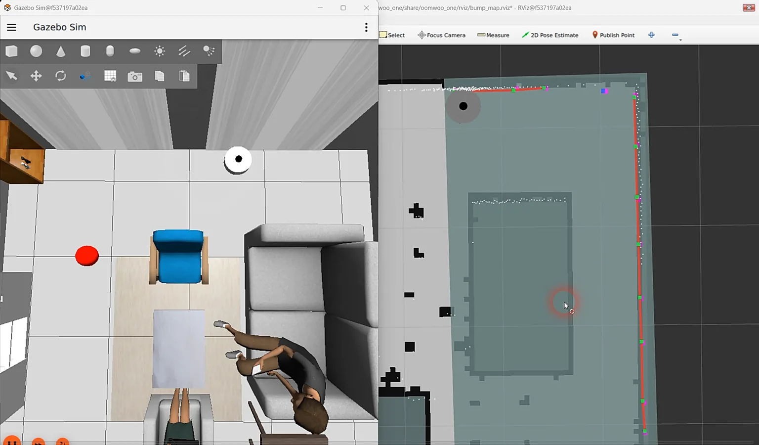
/bump_map/walls segments and the green /bump_map keep-out layer over the SLAM map.Everything runs in the same dev container. Start the sim, localize so the map frame exists (navigation.launch.py now auto-seeds the known start pose in simulation – no manual RViz “2D Pose Estimate” needed), and point a single RViz window at bump_map.rviz to watch both the drive and the growing bump map at once:
# terminal 1 - simulator
ros2 launch oomwoo_gazebo world.launch.py

# terminal 2 - localize + one RViz window (navigation + bump map)
ros2 launch oomwoo_bringup navigation.launch.py use_sim_time:=true   map:=/ros_ws/src/oomwoo_gazebo/maps/living_room.yaml   rviz_config:=bump_map.rviz

# terminal 3 - point the vacuum at a wall, then let it bump-out clean
# (wall_clean_bump_out starts the bump_map node for you; bump_map:=false to skip)
ros2 run kaiaai_teleop teleop_keyboard
ros2 launch oomwoo_clean wall_clean_bump_out.launch.py use_sim_time:=true
Watch the red /bump_map/walls segments fill in over the SLAM map; the semi-transparent /bump_map keep-out overlay ships off by default to keep the view clean – tick it on in the Displays panel if you want to see it. Both nodes are live-tunable with kaia set clean.<name> (cruise speed, peel-off and corner turn angles) and kaia set bump_map.<name> (contact radius, segment gap) – change a value and relaunch that one node.

Following any shape with the LiDAR
The bump-out above cleans edges by touch. The next step is doing it before contact, off the LiDAR, so the robot can trace any continuous shape: a wall, the inside corner where two walls meet, and the outside corner of a chair leg. That is what a vacuum is really doing when it cleans around things, and it is what turns edge cleaning from a wall-only trick into something general.
The follower locks onto the surface on its right, holds a fixed standoff and steers on two errors: how far off the target distance it is, and how far from parallel it points. Inside corners fall out of the same law, since the surface curves toward the robot and it turns away. Outside corners do not, because the wall simply ends, so they get an explicit recovery: lose the wall, arc toward where it was until it comes back.
One early surprise: approaching a wall from a metre out, the robot turned parallel and then crawled in at its speed floor. The speed ease-off keyed off the bearing error, but a large bearing error is exactly what a legitimate approach looks like, so the follower throttled itself the moment it angled in. It is a cascade now: the outer loop turns distance error into a desired approach angle, capped at 40°, and the inner loop steers onto that angle, with the ease-off keyed to the inner error. It closes at full speed and straightens on arrival.
Do not steer on the nearest beam
The first version steered on the single nearest beam. In a live capture the distance loop held to about 3 cm while the bearing error thrashed ±20° frame to frame, the heading command mirroring it exactly. The controller was steering on noise.
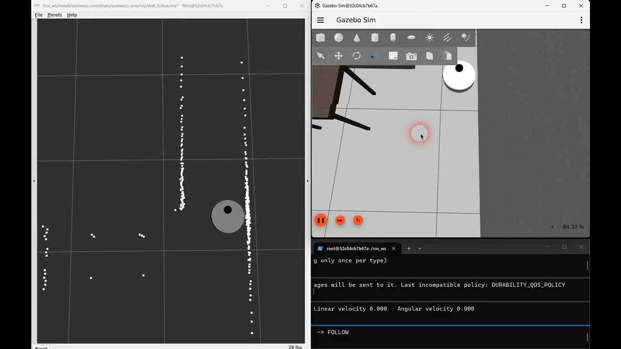
The reason is geometry. Near perpendicular, range barely changes with angle: at a 0.20 m standoff, swinging 20° changes the measured range by 1.3 cm, while the LiDAR’s beam-to-beam scatter is about 2 cm. So which beam is nearest is essentially random across a wide arc. Worse, the minimum of noisy samples is biased low, which is part of why the robot hugged the wall closer than asked.
The fix is to stop asking one beam. The follower seeds on the nearest beam, grows the contiguous surface around it, and fits a line through that whole run of points by total least squares, reporting the fitted perpendicular distance and the bearing to it. Every point contributes, so the noise averages down, and the wall angle falls straight out of the fit instead of being inferred. On synthetic data it is exact on clean input and lands within 0.5° with 2 cm of noise, where nearest-beam gave ±20°. It fixed the wiggle, and broke two other things.
Fit a circle, not a line
The line fit fixed the wiggle and broke two other things. At an inside corner there is no gap in the scan, so the surface kept growing around the corner and onto the next wall. One line through both walls reads about 10° tilted, so the robot began turning away some 0.8 m early and arced gracefully from wall to wall instead of cleaning into the corner. And a table leg is not a line at all: on a 3 cm leg the line fit gave ±15° of bearing noise.
The obvious cheap fix is a median filter on the scan. It does not work. Median-3, median-5, median-9 and repeated passes all left 6–8° of bearing noise, against about 7° unfiltered. The problem is not outliers: the minimum along a wall is flat, and smoothing the ranges never makes it any sharper.
What works is fitting a circle to a short window, 15 cm either side of the nearest beam. On a flat wall the circle’s curvature goes to zero and it becomes the line fit again; on a table leg it bends around the leg. The short window keeps the next wall out of the estimate until the robot is actually at the corner, so the turn now starts at the 0.20 m standoff instead of 0.8 m out.
| Surface | Nearest beam, median-5 | Line fit | Circle fit, 15 cm window |
|---|---|---|---|
| Wall | +0.4° / 7.4° | 0.0° / 0.1° | 0.0° / 0.7° |
| Inside corner, 0.8 m ahead | −0.5° / 7.8° | +9.8° / 0.1° | 0.0° / 1.0° |
| 15 cm stool seat | −0.1° / 4.5° | 0.0° / 1.2° | 0.0° / 0.4° |
| 3 cm table leg | −0.1° / 1.9° | +2.3° / 14.7° | 0.0° / 0.4° |
One catch: on a thin leg the fit has only about 15 points to work with, and roughly 1% of the time it settles on a tiny circle nowhere near the surface. A live run caught one pointing behind the robot, and a single frame like that commands a full-speed turn. Each fit is now checked against the beam it started from and thrown away if the two disagree. That cut the worst case from 99° to about 30°, and the check never fires on a wall.
The wall that followed the robot
Part way through, a wall appeared in the scan about a metre ahead and followed the robot everywhere, through spins and drives. It was not a leftover test obstacle, and not the depth camera. It was the floor.
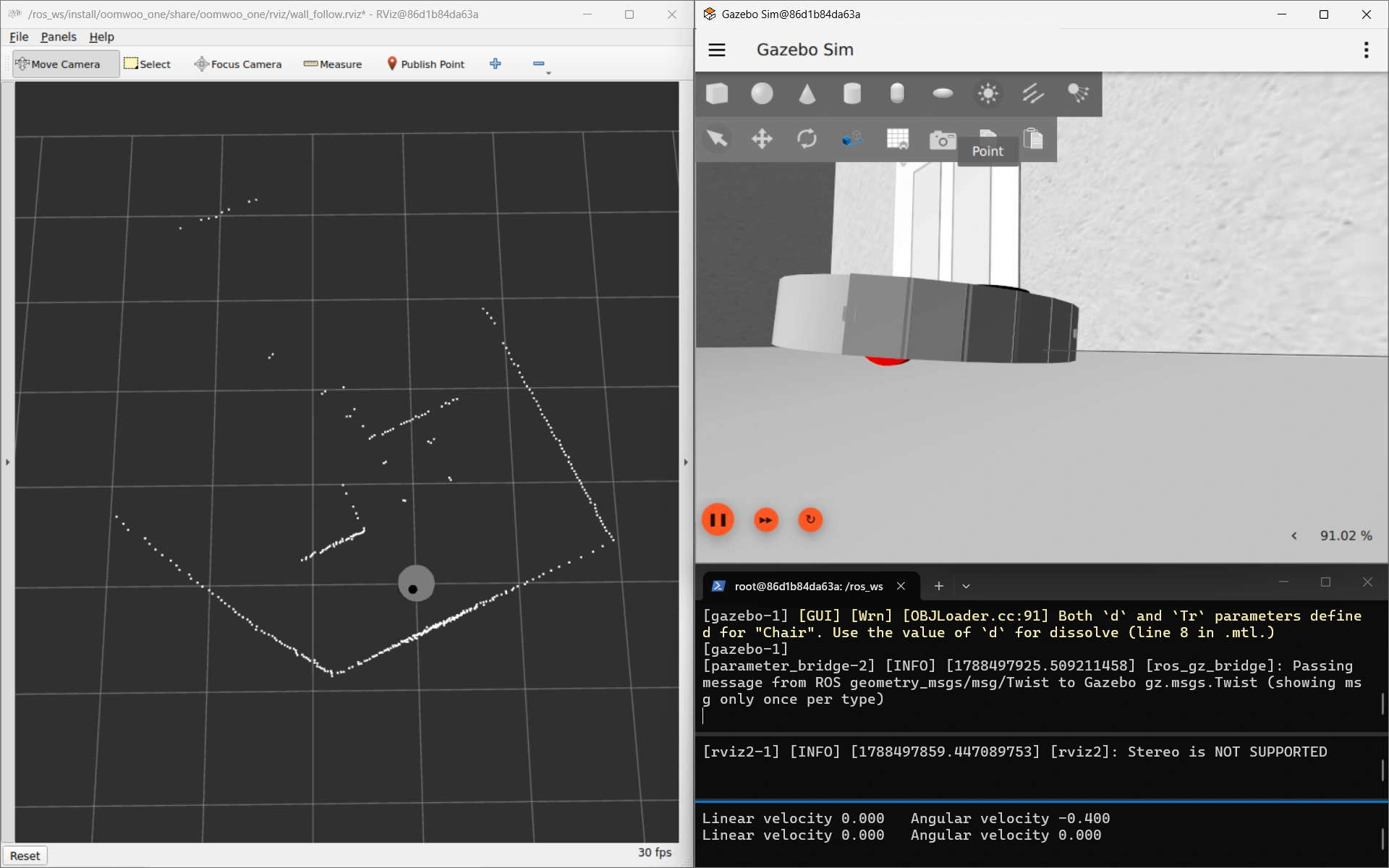

In a captured scan, range times the cosine of bearing was constant at 1.07 m across a 44° span, which is the signature of a flat plane square to the heading. Gazebo reported the robot pitched 3.97° nose down, and the angle at which the front edge of the body reaches the floor, asin(ground clearance / body radius), is 4.11°.
The cause was a change made for this very feature. Moving the LiDAR forward, to see around corners sooner, pushed the centre of mass 1.6 mm past the wheel axle, and the only thing holding the tail down was a single rear caster. The robot tipped onto its nose and aimed its scan plane at the floor about a metre out, quietly corrupting wall following and scan matching at the same time.
The fix was to move the caster to the front, which inverts the requirement: with the caster ahead of the axle, the centre of mass has to be ahead too, which is exactly what the forward turret provides. It now sits 7.2 mm ahead, the robot stands level, and it takes 4.31 m/s² of forward acceleration to unload the caster against a 1 m/s² limit: a 4.3x margin in place of a 1.6 mm one. Two parameters that looked independent turned out to be one decision.
A torture course, and a two-second rehearsal
Watching the robot in RViz only goes so far, so the follower now has a Gazebo course built to break it. A 5 × 5 m room holds a square pillar, a 3 cm fin whose free end the robot has to wrap 180° around, a round pillar, a coffee table’s four 4 cm legs, a 45° wall, a 50 cm corridor, a concave alcove, and a 6 cm lip. Each one stands on its own, so a failure names itself.
The lip cannot be passed, and that is on purpose. The LiDAR scans 8.8 cm above the floor, so it looks straight over a 6 cm obstacle; only the bumper can find it. It stays in the course so the missing bumper handoff stays in plain sight.
ros2 launch oomwoo_gazebo world.launch.py world:=contour_torture.world odom_source:=robot_wheels
ros2 launch oomwoo_clean contour_follow.launch.py use_sim_time:=true
A Gazebo run takes minutes, though, so there is also a 2D rehearsal. It drives the follower’s real boundary estimator and real steering around a ray-traced floor plan, with a simple model of the robot that includes where the LiDAR is mounted. A 40-second scenario finishes in about two seconds, so it runs on every commit, and a question like “does this survive a table leg?” gets a number before Gazebo is even open.
python3 -m oomwoo_clean.contour_harnessKeep the shell clear, not the LiDAR
In Gazebo the robot circled a table leg, then carried on along the couch and hit the next leg. The rehearsal reproduced the problem straight away: wrapping the end of a wall brought the centre of the body to 0.169 m from it, against a body radius of 0.1745 m. That is contact. A box corner came out at 0.174 m, half a millimetre inside it.
Two fixes that sounded right made it worse, and the rehearsal caught both within minutes:
- Feed the curve’s radius forward into the steering. Clearance around a table leg fell from 0.178 m to 0.048 m as the robot spiralled inward.
- Slow down in tight turns, the way commercial robots visibly do. Clearance fell to 0.083 m. In this controller the turn rate comes from the bearing error, so cutting the speed while the turn rate holds shrinks the turning radius, and the robot curls in.
The real cause was geometric. The follower was holding 20 cm between the LiDAR and the surface, but the LiDAR sits 7.45 cm ahead of the wheel axle. In a tight turn the body swings wide of where the LiDAR points, so a perfectly held standoff still lets the shell brush past. The fix is to measure the same 20 cm from the centre of the body. It needs no new sensor: the fitted circle is just a curve, and the body centre is one more point to measure it from.
| Scenario | Holding the LiDAR at 20 cm | Holding the body at 20 cm |
|---|---|---|
| End of a wall | 0.169 m (contact) | 0.181 m |
| Box corner | 0.174 m (contact) | 0.180 m |
| 2 cm table leg | 0.182 m | 0.196 m |
| Room walls | 0.186 m | 0.193 m |
Driving parallel to a wall, the body centre is directly behind the LiDAR, so both measurements are identical and ordinary wall following is untouched. They only diverge in turns, which is exactly where the robot was brushing things.
One thing it does not change: circling a leg, the robot still points about 18° nose-out. That is proportional steering doing what it was told. The turn has to come from somewhere, and the only input is the bearing error, so the robot settles where that error supplies the turn: 0.45 rad/s ÷ 1.5 ≈ 17°. With the body measured correctly, that lean no longer costs clearance.
Seen, but never picked
With the shell measured correctly, the follower passed every shape the rehearsal gave it. Its first run on the Gazebo course found one it cannot handle. The robot followed a wall straight into the end of a panel standing just off it.
Part of that was the course’s fault. The panel was 27.5 cm from the wall, and the robot is 34.9 cm wide, so that was a slot it could never fit through. Checking every gap in the course turned up one more like it and three tight squeezes. The course is now laid out so no gap is narrower than 45 cm, and a crash there means the follower failed, not the course.
The rest was a real gap in the follower. The panel’s end was in view for the whole approach, 5° to 16° left of straight ahead. But the follower steers on the single nearest surface, and the wall beside the robot was always nearer. By the time the panel end was as close as the wall, it had moved past the edge of the area the follower searches, 20° left of the nose, and dropped out of view. It was never picked. An earlier collision with a second table leg turned out to be the same thing, and the rehearsal now reproduces it on demand.
The proper fix is a front guard that watches the robot’s own path, whichever surface it happens to be following. Until then, the robot simply stops dead the moment a bumper touches anything and logs what it thought it was following. That leaves each collision exactly where it happened, ready to be looked at.
Next up were that front guard, then loop closure (the robot would circle a lone table leg forever, because nothing told it that it had been all the way round; the cleaning manager below now handles that), and a bumper handoff for anything below the LiDAR.
A lap of the torture course
Here is the whole thing running: LiDAR only, no map, no SLAM, in a 6 × 6 m room whose walls are lined with the shapes that break a wall follower. A peninsula juts in from one side and folds the course back on itself, so the boundary stays a single continuous wall and the robot traces the perimeter and both faces of the peninsula without ever having to decide where to go next. A lap takes about four minutes.
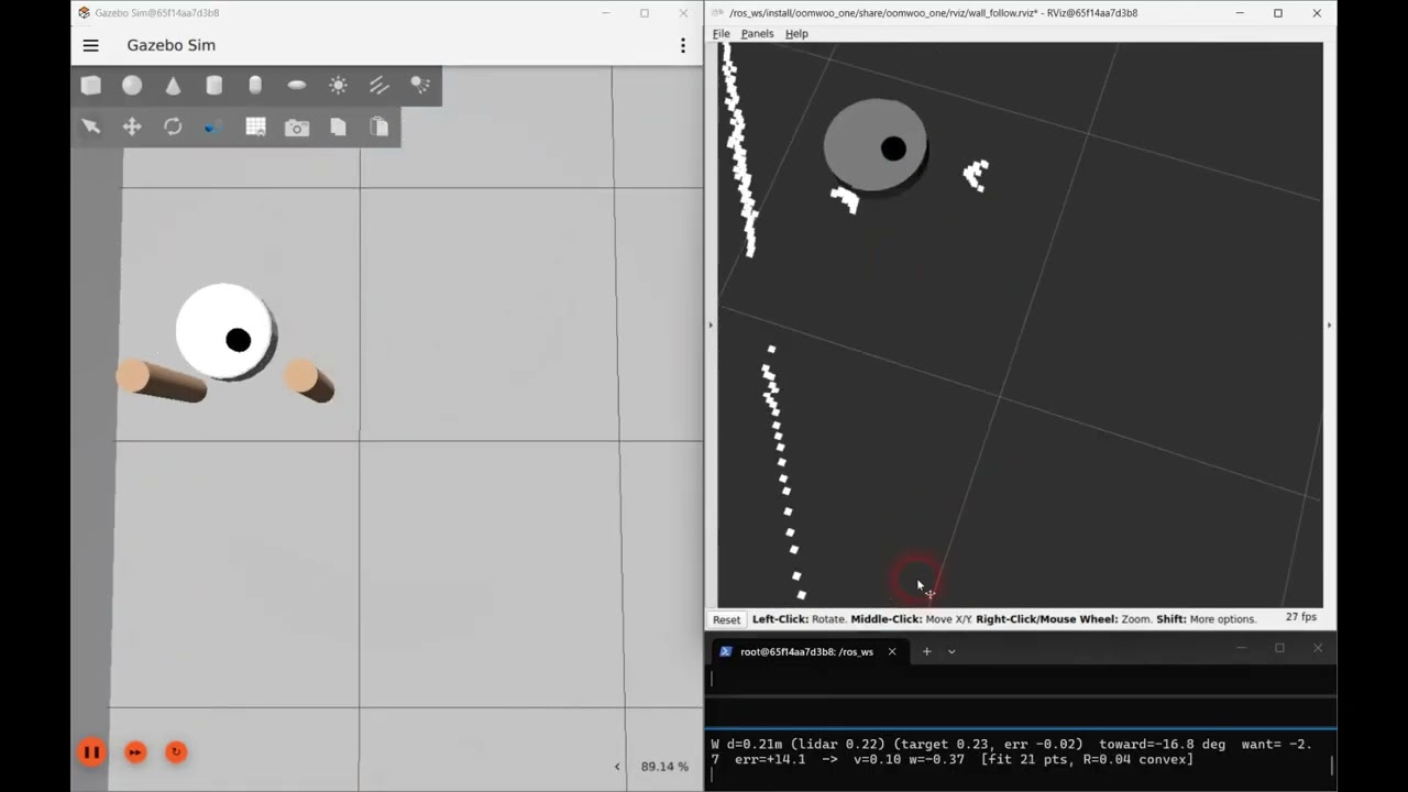
Going round: four square teeth with gaps of 2.0, 1.1 and 0.9 robot diameters; a small then a wide block; a table leg, two legs in a row and two thicker legs; the 180° wrap at the peninsula’s tip; blocks standing 25 cm and 50 cm off it; a convex half-cylinder; a wedge; a concave bay it fits into and a tighter one it does not; and a V-shaped pocket that narrows as you go in.
How hard to steer back to the wall
The cascade has one number that matters more than the rest: how steep an approach angle each centimetre of distance error asks for. It started at 2 (radians per metre), which is about 1° per centimetre. Along a straight wall that is plenty. Around a table leg or a box corner it is not, because a proportional controller has to hold an error to keep turning, and the error it settles at is whatever the turn needs, divided by this gain. In Gazebo the robot wrapped every sharp corner 3–4 cm inside its standoff, and now and then it touched.
Raising the gain shrinks that error in proportion. Raise it too far and the robot overshoots the standoff, swings back, overshoots again: it weaves. Along a straight wall the loop behaves like a spring with a damper, and the damping works out at about √(2.5 / gain) at full speed. That is 0.65 at a gain of 6, 0.46 at 12, 0.32 at 25 and 0.16 at 100; visible weaving starts somewhere around 0.3. To find the edge for real, the robot drove a full lap of the course at each gain, with the simulator’s ground truth recording how close it came to everything.
| Gain | Closest pass | Time closer than 20 cm | Bumps |
|---|---|---|---|
| 2 (the old setting) | 17.4 cm | 10.4% | 1 |
| 6 | 18.6 cm | 2.0% | 0 |
| 12 (the new default), two laps | 19.0 / 19.6 cm | 0.3% | 0 |
| 15 | 19.8 cm | 0.1% | 0 |
| 25 | 20.0 cm | 0.0% | 0 |
| 40 | 17.4 cm | 1.1% | 1 |
| 100 | 17.4 cm | 2.4% | 1 |
Up to 25 the robot comes closer to holding its distance with every step, and nothing touches. At 40 its turn rate swings more than twice as hard as at 6, it slows itself down, and it bumps. At 100 it weaves ±16 mm along a plain wall. So the usable range tops out around 25, and the default is now 12: every centimetre off the standoff asks for about 7° of approach angle, with twice that before the weaving starts.
Two things the laps ruled out or turned up along the way. Wheel slip, visible in the Gazebo view during turns, is not what was pulling the robot in: measured against ground truth, the robot turns at 98% of the rate it is told to. And at a gain of 10 the robot met the pair of thin legs, locked onto one of them and circled it for four minutes, until the run ended. That was not the gain. A lone leg looks like a complete obstacle, and until the follower can tell it has been all the way round, one can capture it at any gain.
What the follower does with each scan
Everything above accumulated one fix at a time, so here is the whole loop in order. Ten times a second, for each new LiDAR scan:
- Look only where the wall should be. A sector from 170° behind the robot to 20° past its nose, on the follow side, ignoring anything more than 1 m away, so “the nearest surface” means this obstacle and not the far side of the room.
- Take the nearest beam, then stop trusting it. It marks which surface to follow; on its own it is too noisy to steer by.
- Grow the surface around it — 15 cm either way along the scan, breaking wherever the range jumps by more than 10 cm, so an inside corner does not drag the next wall into the estimate.
- Fit a circle to that window. On a flat wall the curvature comes out at zero and it is simply a straight-line fit; on a table leg it bends around the leg. One estimator, any shape.
- Check the fit against the beam it started from and throw it away if the two disagree, which happens on a thin leg about 1% of the time.
- Measure from the middle of the robot, not from the LiDAR, which sits 7.5 cm ahead of the wheels — in a turn the shell swings wide of wherever the LiDAR is pointing. And never report a surface as further away than the nearest scan points say it is, because a fitted circle rounds off a sharp corner that is not round.
- Turn that into two numbers: how far the surface is from the 23 cm it should be, and how far its nearest point is from straight out to the side.
- Steer as a cascade. The distance error sets a desired approach angle, about 7° per centimetre and capped at 40°; the difference between that and the actual angle sets the turn rate. Speed eases from 15 cm/s down to 5 cm/s as that inner error grows, so the robot slows for corners and runs at full speed down a straight wall.
- If the surface vanishes — an outside corner, where the wall simply ends — arc toward the follow side until it comes back. Lose the wall, curve toward it.
No map, no localisation, no plan: it is a scan-to-wheels reflex, and the whole state is the four or five numbers it carries between scans. That is deliberate. Cleaning the edge strip is the one job where a reactive behaviour beats a planner, because the wall in front of the robot right now is more accurate than any map of it.
What it still gets wrong, all visible in the video: it skips gaps narrower than about two standoffs (the 1.1-diameter gap between two teeth is wide enough for the robot, but not for a path that keeps 23 cm off both sides), it could clip a thin table leg or a sharp corner now and then (much rarer since the steering gain went up, above), on its own it has no loop closure, so nothing tells it when it has been all the way round (the cleaning manager, next, supplies that), and it has no front guard: something standing in its path that is further away than the wall it is following is never steered around.
Every edge once: tracking what has been cleaned
The follower on its own never knows when to stop. Give it a lone table leg and it goes round and round: during the steering-gain tests above it did exactly that for four minutes, until the run ended. So a small cleaning manager now sits on top of it, with a map and a job list.

What counts as an edge. The manager takes the map and finds every spot exactly the follower’s standoff, 23 cm, from an obstacle. Those spots form rings: one round each table leg, one long ring round the room. That is where the robot’s centre runs while it cleans an edge, so the rings double as the to-do list. A gap too narrow to clean along has no ring in it at all, because no spot in it is 23 cm from both sides.
Ticking edges off. As the robot moves, every ring spot its centre passes close to is marked swept, but only while the follower is driving. Being driven past an edge by Nav2 does not count; the point is to have run along it. Separately, all the floor under the robot is marked cleaned.
Knowing when to stop. For each swept spot the manager also remembers how far the robot had driven when it got there. When the robot is back on its own track from more than a metre of driving ago, and stays on it for 30 cm, it has come full circle: round the leg, or back to where an earlier stretch began. The manager stops the follower there and moves on. That is the loop closure the follower never had, and the same rule ends a lap round a 2 cm leg and a lap round the room.
Moving on. The next target is the nearest edge still dirty, measured along the floor through gaps the robot fits, not as the crow flies: a wall just the other side of a partition is not near. Nav2 drives there and parks facing along the edge with the obstacle on the right, and the follower takes over. When nothing dirty is left, the manager prints a report and exits:
EDGE CLEAN DONE in 8m 46s: edges 99.0% swept (~43 of ~44 m; ~0.2 m written off),
floor passed over 16.7 of 31.7 m2, driven 56.4 m, 6 segments
The floor figure is only what an edge pass reaches; the open floor in the middle is the room-coverage planner’s job. The robot’s position comes from the localizer, not from the simulator, so the same node runs on a real robot.
Three things the first runs taught it:
- Start where the dirt starts. The first version sent the robot to the nearest dirty spot, which was often the far end of a dirty stretch. The follower only drives forward, so it ran straight onto clean edge, stopped, and gave up on the rest: one table leg took three short hops and a third of it was left. Now the manager walks back along the dirty stretch to where it begins, plus 10 cm, because Nav2 only parks within 15 cm of its goal. Replaying that same run: one pass, all of it. Edge swept went from 97.1% to 99.0%, and edge given up on from 0.9 m to 0.2 m.
- Give up on a spot, not on the map. A spot Nav2 cannot reach, or the follower cannot trace, is written off (cyan) rather than retried forever. But when three different targets fail in a row, the robot is what’s stuck, not the targets, so the run stops and says so instead of quietly writing off the rest of the room.
- Nav2 had a blind spot for thin walls. In the first run the robot sat on open floor, facing straight down its own planned path, for ten minutes. Nav2’s DWB controller scores every candidate move against all of the plan within a few metres, and a plan that U-turns round the end of a thin wall lies on both sides of it. Driving forward stopped scoring any better than standing still (both came to 48.48, and the tie went to standing still). The same thing will happen at a room divider or an open door. The robot now uses Regulated Pure Pursuit, which chases a single point 40 cm ahead on the path and ignores the rest: stuck at 94% of the edges before, done at 97% in eight minutes after.
Where it is still loose. Cleaning is marked where the robot believes it is, and a mark stays put when the localizer later corrects itself. Measured against the simulator’s ground truth, AMCL is typically 3.4 cm off and 12 cm at worst, which is the pale green you can see shift against the edges in the video. The fix is sharper localization: the slam_toolbox localizer described further down, once the course has a pose graph for it.
Try edge cleaning
Four terminals. The map is drawn from the same layout as the world, so the two line up exactly:
ros2 launch oomwoo_gazebo world.launch.py world:=contour_torture.world \
  x_pose:=-2.6 y_pose:=-2.77 odom_source:=robot_wheels
ros2 launch oomwoo_clean nav.launch.py x_pose:=-2.6 y_pose:=-2.77 \
  map:=$(ros2 pkg prefix oomwoo_sim_support)/share/oomwoo_sim_support/maps/contour_torture.yaml
ros2 launch oomwoo_bringup monitor_robot.launch.py use_sim_time:=true \
  rviz_config:=edge_clean.rviz
ros2 launch oomwoo_clean edge_clean.launch.py
The last one starts the follower and the manager together; the follower waits for the manager to send it to its first edge. The code is in oomwoo_clean: clean_manager_node.py runs the job, and edge_sweep.py does the bookkeeping with no ROS in it, so the whole loop can be tested offline in a few seconds.
Docking: a beacon to point, the LiDAR to aim
A robot vacuum has to find its way home to charge. OOMWOO’s dock is a hollow bay that the robot reverses into, because the charging contacts (and, on the full build, the mop wash) are at the back. The bay is 40 cm wide and the robot is 35 cm across, which leaves about 2.5 cm on each side, so “roughly over there” is not good enough. The robot has to arrive centred and square. Here it is docking in the simulated kitchen, from a series of starting spots:
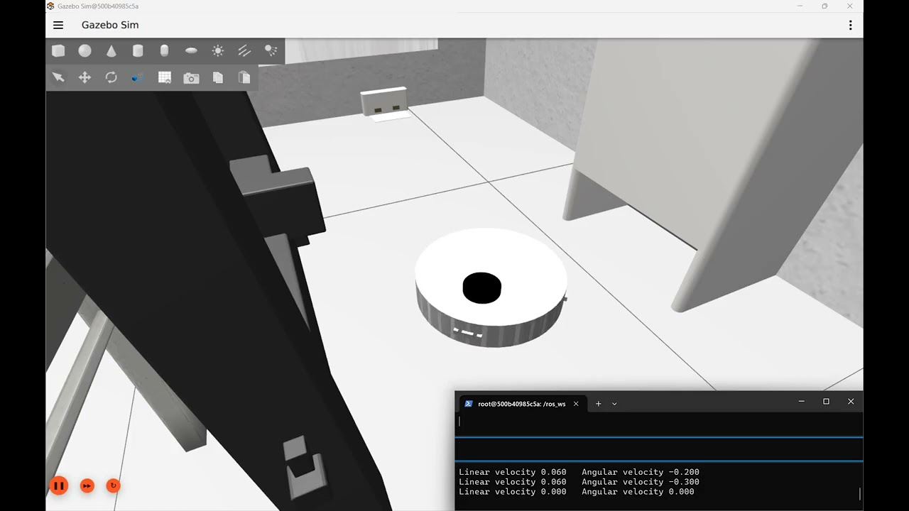
Five steps home
- Turn in place until the beacon shows up. The dock has an infrared beacon at the back of its bay, and the robot has two IR receivers at its back. When both receivers see the beacon, comparing how strongly each one sees it gives the beacon’s direction. The robot stops turning there.
- Find the dock with the LiDAR, and make sure. The beacon gives a direction but not a distance, so the LiDAR does the measuring. The robot fits the dock’s known outline to the scan at the spot the beacon points to, which places the dock to about a centimetre. It won’t move until two scans in a row agree on that position.
- Drive to the staging point. That’s a spot centred in front of the dock, 35 cm from the mouth of the bay, so the robot’s tail ends up just short of the dock’s tray. The robot drives onto the dock’s centreline first, then along it to the staging point. Cutting diagonally across the front of the dock risks clipping a side panel.
- Turn round until its back faces the bay.
- Back in slowly, steering to stay centred and square. The robot only crosses into the bay once it is within 2.5 cm of the centreline and 5° of square. Otherwise it pulls back out to the staging point and tries again, up to three times. It also stops 1.5 cm short of the back wall and lets the last bit of travel close the gap. If it tried to stop exactly flush, a small error in its estimate would leave it pushing the dock across the floor.
Why both a beacon and a LiDAR
The first version used the LiDAR alone, and it taught us that the LiDAR is excellent at saying where the dock is but poor at saying which thing is the dock. A dock standing against a wall makes a convincing false match about 20 cm to one side: the wall plays the back of the bay and one of the dock’s real side panels plays a wall of the bay. The fit can score that false match better than the real dock. We added more and more tests to catch it. The one that mattered checks that the fit sees both sides of the bay, since the false match only has one. But from well off to one side, the dock’s far side panel is hidden behind the near one. Then the test rejected the real dock too, and the robot sat there forever.
The beacon settles it. A fit that puts the beacon where the receivers actually see it is the dock, even if the far side of the bay is hidden. The false match misses the beacon’s direction by about 12°, far more than the receivers’ error. So the two sensors split the work: the beacon says which thing is the dock, and the LiDAR says exactly where it is. In the test rig, from 64 parked positions in a furnished room (walls, a dining table, two chairs), the robot docked from 60 with the LiDAR alone and 63 with the beacon. It never touched the dock. On the twelve spots the automated tests check, the worst it arrived off-centre was 4.5 mm.
What the beacon can see
Gazebo has no infrared sensor, so a small simulator node works out what each receiver would read from the robot’s true position. Modelling it made two limits obvious, and both are geometry rather than electronics. First, the beacon sits at the back of the bay, so its light only escapes through the mouth, within about 40° either side of straight out from the dock. A robot parked beside the dock sees nothing, however good its receivers are. That is the one parked spot in the test that never docks with the beacon. Second, the receivers face backwards, angled 25° either side, with a small divider (a baffle) between them. Both see the beacon only when the robot’s back points within about 20–25° of it, which is why step 1 is a turn. If the robot ever needs to find the dock from further round the side, a second, wide-angle emitter on the dock’s front would cover that, leaving the recessed one to do the precise lining up.
Forwards to the staging point
In the video the robot backs up to its staging point in curving arcs, which works but looks odd. It is also blind: the bumper is at the front, so anything the robot reverses into goes unnoticed. Now it turns in place to face each point and drives there forwards, and only the last leg, into the bay, is driven in reverse. Turning before driving matters. An earlier forward-only version turned while it drove, so a point behind the robot became a wide loop, and in the test rig that loop sometimes ran straight through the dock. Driving straight lines also improved the line-up: on those twelve test spots, the worst off-centre arrival dropped from 14 mm to 4.5 mm.
Still missing: while driving to the staging point, the robot has no obstacle sensing of its own. It goes by the dock’s position alone, so anything in the way is found by the bumper.
Try docking
Everything runs in the OOMWOO dev container, with no robot needed. To watch in Gazebo’s window you need a display for the container; Simulate OOMWOO-One shows how to set that up. Or run it headless and follow along in the terminal.
1. Get the container. Pull the image even if you already have it, because docking is newer than most copies. If you have an oomwoo container from an older image, remove it first with docker rm -f oomwoo.
docker pull makerspet/oomwoo:jazzy-devSpin up the container – read this article for setup instructions.
Windows WSL2
docker run --name makerspet -it --rm -v c:\maps:/root/maps -p 8888:8888/udp -p 5555:5555/udp -e DISPLAY=host.docker.internal:0.0 -e LIBGL_ALWAYS_INDIRECT=0 --add-host=host.docker.internal:host-gateway makerspet/oomwoo:jazzy-devUbuntu
docker run --name makerspet -it --rm -v ~/maps:/root/maps -p 8888:8888/udp -p 5555:5555/udp -e DISPLAY=$DISPLAY -v /tmp/.X11-unix:/tmp/.X11-unix --network host makerspet/oomwoo:jazzy-dev2. Start the kitchen. In that shell, start the kitchen world. The robot appears just in front of the dock with its back to it. Add headless:=true to run without UI.
ros2 launch oomwoo_gazebo world.launch.py world:=kitchen_dining.world3. Dock. Open a second shell into the same container and start docking. This runs the dock detector, the docking driver and the simulated IR beacon. The launch ends by itself once the robot is docked, and the last lines say how well it lined up:
docker exec -it oomwoo bash
ros2 launch oomwoo_sim_support dock_sim.launch.py use_sim_time:=true

# ...
# [dock_drive]: docked: lateral +4.0 mm, yaw +0.47 deg
# [dock_drive]: docking complete; exiting
To follow the steps as they happen, echo the docking state in a third shell. It goes SEARCH, GOTO, TURN, BACK, DONE, with REGROUP if the robot pulls out to try again. The launch’s exit status is 0 when docked and non-zero when it gave up, which is handy in a script.
ros2 topic echo /dock_drive/state4. Park it somewhere else and dock again. Drive the robot with the keyboard to anywhere in front of the dock. It doesn’t need to face any particular way, because it turns to find the beacon itself. Then stop the robot and quit teleop (Ctrl-C) before repeating step 3, so the two aren’t both steering the robot:
ros2 run kaiaai_teleop teleop_keyboardFor a start you can repeat exactly, restart the world with a different x_pose and y_pose instead. The positions are in the kitchen’s coordinates, in metres. The dock stands against the west wall with its mouth at x = −2.11, y = −0.5, facing +x, and the robot always starts facing +x, away from the dock. We checked these three spots headless; each took between 15 and 25 seconds:
# just in front of the dock (the default)
ros2 launch oomwoo_gazebo world.launch.py world:=kitchen_dining.world x_pose:=-2.0 y_pose:=-0.5

# 0.6 m straight out
ros2 launch oomwoo_gazebo world.launch.py world:=kitchen_dining.world x_pose:=-1.5 y_pose:=-0.5

# 0.4 m off to the side
ros2 launch oomwoo_gazebo world.launch.py world:=kitchen_dining.world x_pose:=-1.6 y_pose:=-0.9
Mind the dining table: it reaches further towards the dock than it looks. At x = −1.5, y = −0.15 the robot starts with its bumper already pressed against the table and cannot turn. That spot never docks, and a real robot parked there would be just as stuck.
Why not just add a cheap ultrasonic sensor?
It comes up every time somebody reads the sensor list: an ultrasonic rangefinder costs about a dollar, so why not ring the robot with them and let it hear obstacles? It is a fair question, and the answer is a nice piece of physics — ultrasound is not bad at measuring distance. It is bad at the particular job a vacuum needs doing.
At 40 kHz, sound in air has a wavelength of about 8.6 mm. Anything smoother than that — painted drywall, a cabinet door, glass, the side of a fridge — is an acoustic mirror. The echo leaves at the same angle it arrived, so a wall approached at a slant bounces the ping off into the room instead of back to the sensor, and as far as the robot knows the wall is not there. Industrial ultrasonic vendors put a number on how fussy this is: for a smooth target they want the sensor within about three degrees of perpendicular. Rough surfaces are more forgiving, because their texture scatters a little energy back. On a robot that is turning most of the time, obstacles wink in and out as it yaws — roughly the worst property a sensor can have when you are trying to build a map out of it.
Two more limits close the case. The beam is a cone fifteen to thirty degrees wide, so a reading means something is at 80 cm, somewhere in that cone — never where. And sound is slow: a four-metre round trip takes 23 ms, the transducer has to stop ringing before it can listen again, and several sensors firing at once deafen each other, so they have to take turns. A ring of eight ends up refreshing each direction about four times a second. The LiDAR already on the robot sweeps a full circle at roughly a degree of resolution, several times a second.
Then there is the furniture. Curtains, upholstery, bedding and pet beds are porous and fibrous, which makes them excellent sound absorbers — an ultrasonic sensor can stare straight at a sofa and hear nothing back. And this is the part I like: that same property is exactly why robot vacuums do carry ultrasonic sensors. Pointed down at the floor, the difference in reflected amplitude between hard flooring and soft carpet is precisely the signal you want. The physics that makes ultrasound a poor obstacle detector makes it a good carpet detector. It did not get rejected — it got moved to the job it is actually good at.
The last argument is commercial. An ultrasonic module’s two 16 mm transducers are bigger than the entire optical time-of-flight array they would replace: a VL53L1X is about 5 x 2.5 x 1.6 mm, costs about the same, and returns millimetre-class range at 50 Hz through a narrow, aimable field of view. To be fair, ultrasound wins somewhere worth respecting — glass and mirrors are invisible to infrared and often to LiDAR, but they are acoustically hard and echo back perfectly well, which is why cars park by ultrasound. If we ever go hunting glass doors specifically, a forward transducer or two is the sensible exception. It is also worth separating the technology from the hobby part: automotive ultrasonic sensors, with tuned horns and coded chirps, are far better than the module most people have in mind when they ask.
Sharper localization — and a built-in lost-alarm
The bump map above has a catch: it places each wall segment at the robot’s estimated pose at the moment of contact. With the stack’s default localizer — AMCL — that estimate drifts a good ten centimetres sideways and a little in heading, so the tactile wall segments came out crooked against the LiDAR map: the live scan points landed cleanly in a line, the map showed the wall cleanly, yet the two stayed visibly apart. Fine for a delivery robot; not for a vacuum that has to know which wall it is hugging.
Why is AMCL loose? It is a particle filter: it keeps a cloud of pose guesses, scores each against a blurred copy of the map, and publishes the cloud’s weighted mean. A mean of a scattered cloud is inherently decimetre-class and jittery — no amount of tuning turns it into a millimetre.
The fix is a different kind of localizer: scan matching (slam_toolbox in localization mode). Instead of averaging particles, it slides and rotates the live LiDAR scan until it best overlaps the map geometry, optimizing the pose directly to sub-cell (centimetre) precision. Point it at the map’s saved pose-graph and the sensed wall lands on the map wall — and the bump-map segments straighten out with it.

The clip runs both localizers side by side: Gazebo on the left, RViz on the right, and live linear and angular error plots as the vacuum bumps out two living-room walls — you can watch each bump register and the wall estimate build. slam_toolbox’s error hugs the floor at a couple of centimetres; AMCL’s — here with the deliberately loose stock settings — rides higher and wobbles. Tightening AMCL’s measurement model narrows the gap, but never closes it: a particle mean cannot match a pose optimizer.
The takeaway is not “always chase centimetre localization.” You don’t need it to clean — right next to a wall the bumper is ground truth, and the reactive cleaner never consults the map. But the bump map is a persistent artifact, and an artifact wants a pose good enough that its walls line up with reality. So the design is: scan matching for the map-frame pose, cleaning still driven by contact. (One honest trade-off for later: scan matching is weak at recovering when the robot is picked up and set down somewhere else — “kidnapped” — where AMCL’s knack for scattering guesses across the whole map wins. So the plan keeps both, and calls the global one only when the robot notices it is lost.)
The same match score tells you when you’re lost
“When the robot notices it is lost” is doing a lot of work in that sentence — so how does it notice? The answer falls straight out of scan matching, which turns out to have a second job. Fitting the scan to the map does not only yield a pose; it yields a score — how well, at that best pose, the beam endpoints actually land on mapped walls. Localized, nearly every beam sits on a wall and the score is high. Pick the robot up and set it down across the room and the score collapses, because the scan it now sees has nothing to do with the map where it still thinks it is. That single number is a localization health check.
slam_toolbox keeps its own match score to itself, so we compute one alongside it: a small node scores the live scan against the map every cycle and publishes the fraction of beams that land on a wall. It is careful to tell “lost” apart from merely “cluttered” — a stray shoe or a nudged chair only knocks out a handful of beams (the score dips), whereas a kidnap knocks out nearly all of them (the score falls off a cliff). When the score stays low, the robot raises a “lost” flag — and that flag is the trigger that calls in the global re-localizer we build next. So, scan matching quietly does two jobs from one fit: it hands you the precise map-frame pose, and the alarm that says the pose can no longer be trusted.
Can we use AMCL to generate the “am I lost” signal? AMCL I-am-lost signal is its covariance (published in the pose message), and on a clean kidnap the covariance stays small and confident while pointing at the wrong place. The only way to make it rise is increase AMCL recovery_alpha_* parameters above zero – but doing that, we found, sabotages convergence, causes AMCL produce wrong poses.
recovery_alpha_slow and recovery_alpha_fast AMCL parameters help the particle filter decide when the robot is lost – by monitoring drops in particle weights, triggering pose recovery. Pose recovery – when the robot is considered lost on its map – is done by injecting random pose particles, spread out over random locations on the map – thus widening the search for the correct pose (i.e. relocalize). This automatic recovery is what makes AMCL (Adaptive Monte Carlo Localization) “Adaptive”.
Reproduce the comparison
A small harness runs the two localizers together and scores each against the simulator’s ground truth, so you can watch the gap live:
# terminal 1 - simulator (robot_wheels = realistic wheel-encoder odom)
ros2 launch oomwoo_gazebo world.launch.py odom_source:=robot_wheels

# terminal 2 - AMCL + slam_toolbox localization + two error meters + RViz.
# nav_params picks the AMCL tuning; navigation_loose.yaml matches the video.
ros2 launch oomwoo_sim_support localization_compare.launch.py use_sim_time:=true \
  map:=/ros_ws/src/oomwoo_gazebo/maps/living_room.yaml \
  nav_params:=/ros_ws/src/oomwoo_one/config/etc/navigation_loose.yaml

# terminal 3 - drive the walls
ros2 launch oomwoo_clean wall_clean_bump_out.launch.py use_sim_time:=true

# plot both errors live in Foxglove Studio (runs in your browser)
ros2 run foxglove_bridge foxglove_bridge
#   open Foxglove -> ws://localhost:8765 -> Plot panel ->
#   /loc_err_amcl/pos_err_m  and  /loc_err_slam/pos_err_m  (+ the yaw_err_deg pair)
Swap navigation_loose.yaml for navigation_tight.yaml to see how far tuning takes AMCL, and pass odom_source:=ground_truth to remove wheel drift and isolate the pure scan-registration gap. The code lives in oomwoo-ros2-tools.
Staying sharp at speed
Scan matching wins at a stroll, but push the speed up and even slam_toolbox can lose the thread: spin the vacuum fast and the live scan cloud drifts off the map walls, then snaps back. The reason is in how it runs — slam_toolbox re-matches the scan to the map on its own schedule and simply adds up wheel odometry in between. At its default cadence those re-matches are spaced far enough apart that a fast spin outruns them: the pose coasts on odometry, the cloud lags reality, and you see a mis-registration until the next match yanks it back.

The fix is to make it re-match on essentially every scan. Three settings do it: minimum_time_interval drops from 0.5 s (about 2 Hz) to 0.1 s, comfortably under the 5 Hz LiDAR period, so no scan is skipped; and minimum_travel_distance and minimum_travel_heading go to zero, so a spin-in-place — which barely translates — still triggers a fresh match instead of being written off as “hasn’t moved enough.” With those tightened, the scan stays welded to the map right through an aggressive spin.

The last wobble: wheel slip
One flicker survives the tuning: spin the vacuum to its top angular speed (2.55 rad/s) and stop it dead, and the scan jumps for a single frame before settling. This one isn’t the localizer’s fault — it’s the wheels. To see it plainly, forget the map for a moment and diff the two odometry sources the simulator gives us: Gazebo’s noise-free ground-truth heading versus the heading integrated from the wheel encoders. The gap between them is pure wheel slip, and its shape tells the whole story.
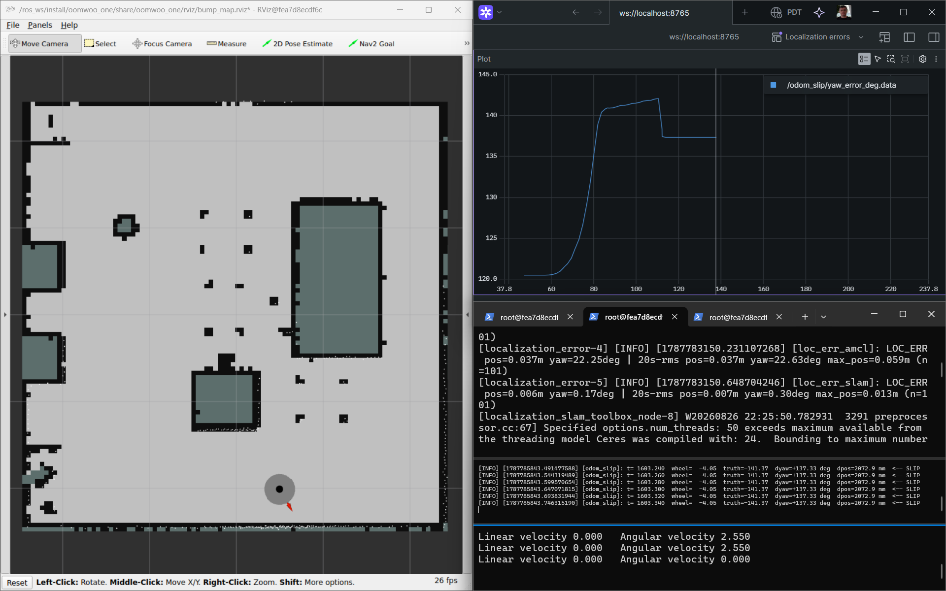
Read it left to right. At rest the error is flat. As the spin accelerates it climbs quickly — the wheels are driven faster than traction can deliver, so they slip forward and the encoders over-count the turn. At top speed the error only creeps, because a steady spin barely slips. Then the abrupt stop: the velocity-controlled wheels halt almost instantly while the body keeps rotating on its own inertia, so the encoders now under-count and the error drops in one step. That inertial overshoot is exactly the single-frame mis-registration, because slam_toolbox’s pose rides on this wheel odometry between matches.

Notice that each aggressive spin-and-stop leaves the error a little higher than it started: the acceleration over-count isn’t fully undone by the stop under-count, so a few degrees of heading drift accumulate every cycle. Over a long run that is how raw wheel odometry wanders tens of degrees from truth — and exactly what scan matching quietly erases each time it re-registers the scan against the map. The slip is faithful physics (a real vacuum’s wheels slip too), just exercised far harder than any vacuum would in normal cleaning. A small odom_slip node publishes it live if you want to watch it yourself:
# spin the robot (robot_wheels = wheel-encoder odom vs /odom_truth)
ros2 launch oomwoo_gazebo world.launch.py odom_source:=robot_wheels
ros2 run oomwoo_sim_support odom_slip --ros-args -p use_sim_time:=true
ros2 run foxglove_bridge foxglove_bridge   # plot /odom_slip/slip_rate_dps and /odom_slip/slip_deg
ros2 run kaiaai_teleop teleop_keyboard     # spin up, then stop abruptly
Why does even a single scan look misregistered, if slam_toolbox re-matches on every one? Because it does not move the scan — it corrects the map→odom transform, and that correction is only ever as fresh as the last matched scan. The pose you see is that last correction composed with the live wheel odometry, and wheel odometry updates at 50 Hz while matches arrive at the 5 Hz scan rate. So the instant a slip step lands in odometry it lands in the displayed pose; it is cancelled only when the next scan is matched — up to one scan (~0.2 s) later. Matching every scan bounds the flicker to that single frame but cannot erase it. At the abrupt stop the wheels freeze while the body coasts on, so the pose under-rotates and the whole scan cloud briefly swings backward against the map, until the next match folds the coast in and it snaps home.
The pose heals itself on the next match, so the answer is not a second corrector. The transient’s only real cost is briefer: for that one frame the scan-versus-map quality dips, and an unguarded dip could raise a phantom dynamic obstacle or a false “lost” alarm. So the dip is treated as a flag under a simple rule — persistence: ignore a single bad frame, act only on a dip that lasts several. And rather than bake that judgment into the quality meter, each consumer of the scan-quality signal owns its own persistence threshold: the dynamic-obstacle detector decides how long a return must persist before it counts as a real object, and the lost-detector decides how long quality must stay low before it calls for relocalization. Measuring the scan stays separate from deciding what a dip means, so each behavior is tuned and debugged where it lives. (An abrupt cmd_vel or IMU acceleration spike can corroborate that a dip is a self-inflicted motion transient rather than a real change in the room — a natural next refinement.)
Does a big obstacle throw it off?
Scan matching leans on the live scan overlapping the map, which raises a fair worry: what happens when something big that isn’t on the map — a person, a couch someone dragged over — blocks a chunk of the view? Does the pose lurch? Rather than guess, we built a repeatable test.
It drops a real 3D wall into the simulator — a solid box the map has never seen, so it occludes the LiDAR physically and simply shows up in the scan. Then we drive the robot up to it and back out while scoring the localizer’s pose against the simulator’s ground truth every frame. To keep it honest we run it twice: once with slam matching the raw scan, and once matching a filtered scan with the off-map returns stripped — the same static-versus-map scoring that raises the lost-alarm, now used to clean the scan before matching.
The result was reassuring, and a little anticlimactic. With the wall throwing roughly a third of the beams as off-map outliers, slam’s position error held around a centimetre and its heading barely moved — filtered or not. The correlative matcher just locks onto the two-thirds of beams that still line up with the map and ignores the coherent off-map chunk. The obstacle never meaningfully moved the pose, so the filter — which cleanly stripped the wall right up until we were nose-to-it — had nothing to rescue. At this scale, scan matching is simply robust.


The test did surface one subtlety worth knowing. In localization mode slam keeps a short rolling buffer of recent scans, and will briefly draw a lingering obstacle into the map it publishes — it heals once you move on, and never touches the saved map on disk, but you would not want even a temporary phantom person baked in. That is the real reason to strip dynamic returns before the matcher, and why the health monitor scores against a fixed saved map rather than slam’s own evolving one. So the scan filter earns its keep as a clean feed for perception and a touch of map hygiene — not as a localization crutch. Good to know which job it is actually doing.
# drop a real wall into the running sim, then drive at it and watch the error
ros2 launch oomwoo_sim_support localization_stress.launch.py use_sim_time:=true \
  map:=/ros_ws/src/oomwoo_gazebo/maps/living_room.yaml rviz:=true
ros2 launch oomwoo_sim_support spawn_obstacle.launch.py x:=0.0 y:=-0.5
ros2 run kaiaai_teleop teleop_keyboard
# add filter:=true to have slam match the obstacle-stripped scan instead
Relocalizing a kidnapped robot
That last trade-off — scan matching is precise but can’t recover when the robot is “kidnapped” (picked up mid-clean and set down across the room) — grew into its own little project. A vacuum really does get kidnapped: you carry it to another room, a child runs off with it, it wakes up somewhere it didn’t drive to. When it comes back it has to answer “where am I?” from scratch, against a map it already holds.
AMCL: global, but a gamble
AMCL’s superpower is exactly what scan matching lacks: it scatters thousands of pose guesses across the whole map, spins the robot in place, and lets the good ones survive. Often it snaps to the right spot within a turn or two:

…and over a run of kidnaps it usually recovers every time:

But “usually” is the problem. It is a random process, and in a room full of look-alike corners it sometimes commits — confidently — to the wrong one: the same L-shaped corner on the opposite side of the room. Here is a single kidnap where it converges to a mirror-image pose and never notices it is wrong:

In our testing AMCL misplaced the robot roughly one kidnap in five, non-repeatably — and, worse, it reported high confidence while doing it. For a product you want a guarantee, not a coin flip.
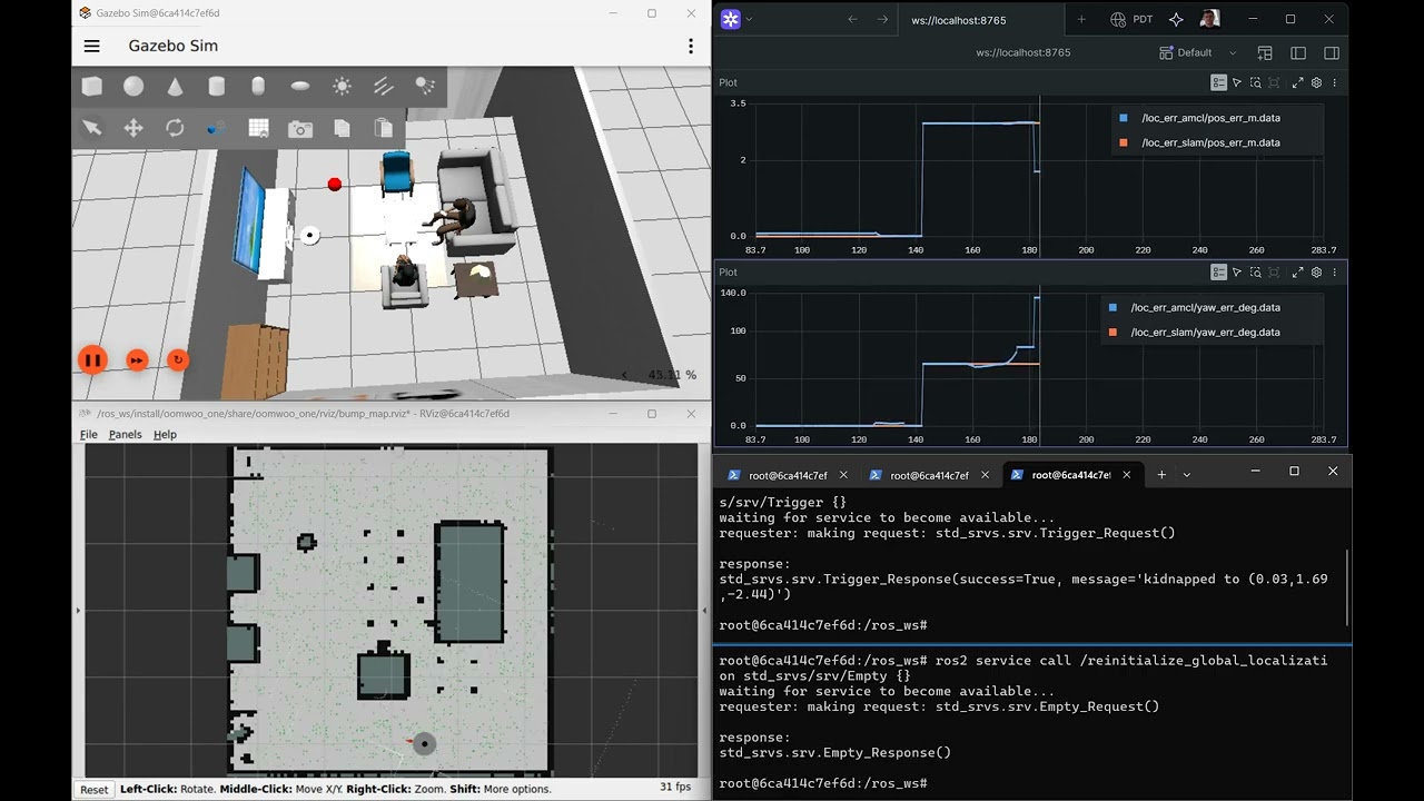
slam_toolbox: precise, but can’t look up
The localizer we chose for precision is no help here at all. Scan matching only refines the pose it already believes, so after a kidnap it simply… stays put, insisting the robot never moved even as the live scan plainly disagrees:
A built-from-scratch global scan matcher
So we built a third option: a global scan matcher that searches the entire map and every heading for the pose whose LiDAR scan best fits the walls — the correlative, branch-and-bound method behind Google’s Cartographer. Because it is an exhaustive search (accelerated with a resolution pyramid so it still runs in milliseconds), it returns the provably best match rather than a lucky one — and it reports a confidence: how much the winning pose beats the next-best candidate. A symmetric room that would quietly fool AMCL comes back flagged as ambiguous instead of silently wrong. Across repeated random kidnaps it relocalizes correctly every time:

That clip also walks through the whole simulation setup end to end on a Windows laptop — pulling the Docker image, pasting the commands, and running the kidnap-and-recover loop — so it doubles as a getting-started guide.
Detect, relocalize, decide — kept separate
The recovery is three small nodes that each do exactly one thing, so policy never leaks into mechanism:
- localization_health — watches how well the live scan matches the map and raises a “lost” flag when the match collapses (a kidnap), but not when a stray shoe or box only dents it.
- global_relocalizer — pure mechanism: given a scan and the map, return the best pose and its confidence. It never moves the robot and never commits anything.
- localization_manager — the policy: on “lost”, ask the relocalizer, then decide. High confidence — commit the pose and carry on. Low confidence — don’t guess: fall back (drive for a better vantage, or go hunt the dock) rather than teleport the map estimate onto a wrong corner.
The everyday localizer stays slam_toolbox scan matching, for its centimetre precision; AMCL and the global matcher are summoned only when the robot notices it is lost. That is the “keep both, call the global one only when needed” plan from the previous section — now built.
Try the relocalizer
Same Docker image as above. Bring up the simulator and the localization scene, then run the lost-detect -> relocalize -> decide chain and kidnap the robot:
# terminal 1 - simulator
ros2 launch oomwoo_gazebo world.launch.py odom_source:=robot_wheels

# terminal 2 - map + localization + kidnap injector + RViz (no auto-spin recovery)
ros2 launch oomwoo_sim_support localization_relocalize.launch.py use_sim_time:=true \
  auto_recovery:=false map:=/ros_ws/src/oomwoo_gazebo/maps/living_room.yaml

# terminal 3 - the recovery chain: health monitor + global relocalizer + manager
ros2 launch oomwoo_localization localization_recovery.launch.py use_sim_time:=true

# terminal 4 - kidnap to a random reachable pose, then watch the decision
ros2 service call /kidnap_injector/kidnap std_srvs/srv/Trigger {}
ros2 topic echo /localization_manager/recovery_action   # "commit" on a confident fix
To call the global matcher directly and read its pose, score and confidence: ros2 service call /global_relocalizer/relocalize oomwoo_localization_msgs/srv/Relocalize {}. The code — the branch-and-bound matcher, the three recovery nodes, and a batch kidnap-grid regression test — lives in oomwoo-ros2-tools.
Prove it across the whole map
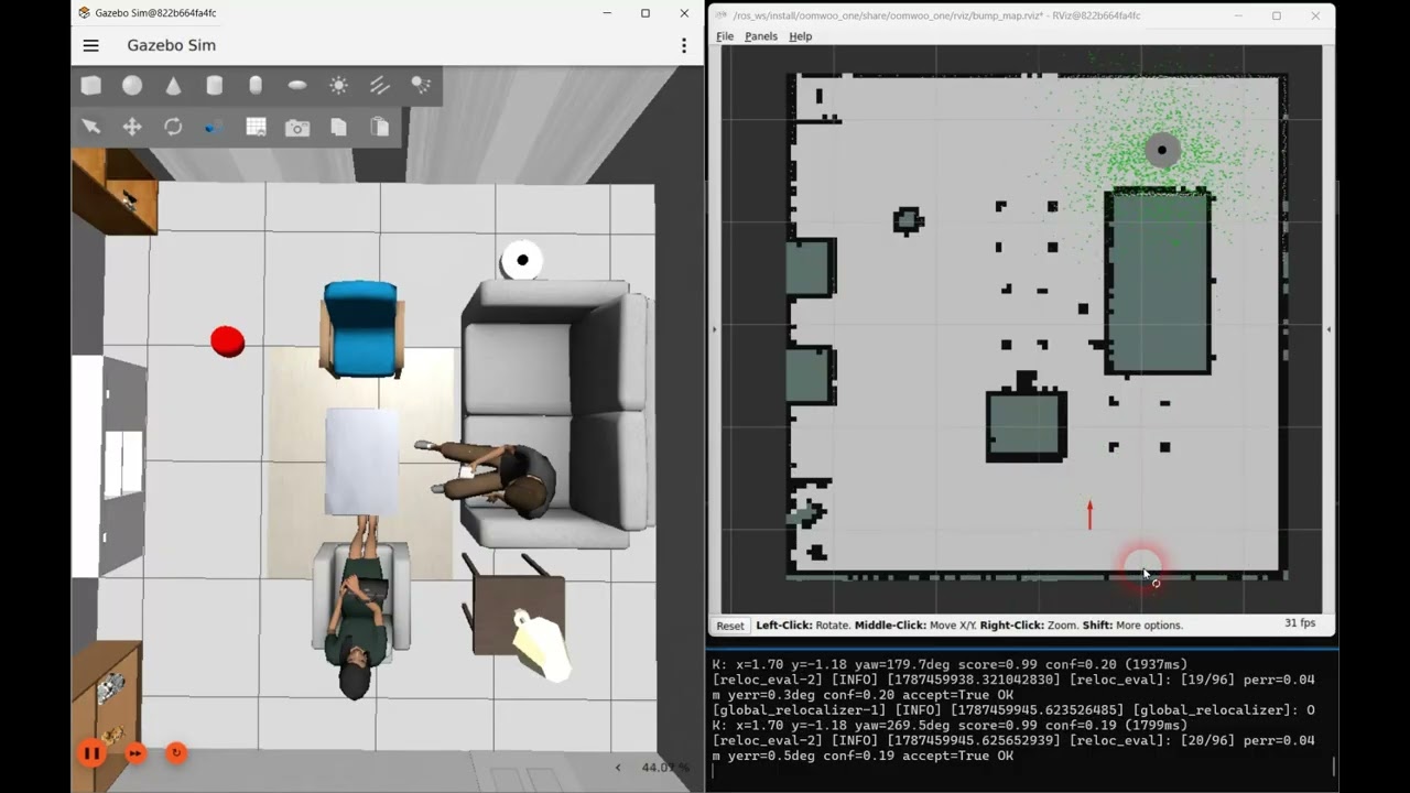
One lucky kidnap proves nothing. A batch harness teleports the robot across a grid of the entire room — every reachable cell, four headings each — calls the relocalizer at each spot, and scores the answer against ground truth. On the living-room map it recovers 96 of 96 poses, to the map’s cell resolution (~3.5 cm) and a fraction of a degree; every fix it accepts is correct, and it attaches a confidence to each so a doubtful match can be refused rather than trusted. It prints a pass/fail summary at the end, so the same run doubles as a regression test. Add publish_initialpose:=true and the robot visibly snaps to each recovered pose in RViz as the grid runs, and hold_s:=3.0 makes it pause on each fix — long enough to watch the live scan settle onto the map — so the whole loop reads clearly on camera:
# terminals 1 and 2 as above (simulator + the localization scene with RViz)
# then the batch evaluation, seeding /initialpose so the robot jumps in RViz.
# hold_s pauses on each fix so the live scan visibly settles onto the map
ros2 launch oomwoo_localization reloc_eval.launch.py use_sim_time:=true \
  publish_initialpose:=true hold_s:=3.0 csv_path:=/root/reloc_eval.csv
Here is the whole grid running: each kidnap teleports the robot, the global search finds it, and — with the pose seeded back for the demo — the robot and its live scan snap onto the map before the next teleport.
Proof it refuses when it can’t tell
Landing 96 of 96 shows the matcher is accurate; it does not yet show the harder, more important thing — that it refuses when it genuinely cannot tell where it is. So the other half of the testing is adversarial: feed the real matcher scans corrupted on purpose and watch the confidence, not just the pose. A stray obstacle blocking a tenth of the scan, or a wall that has been taken down since the map was made, barely dents it — the fix still lands and is accepted. But drop the robot into a symmetric room, where two different poses produce an identical scan, and something telling happens: the match score stays pinned near 1.0 — the scan really does fit that well — while the confidence, the margin over the next-best candidate, collapses to zero. The gate refuses. It picked one of the twins, as any matcher must, but it declined to believe it.
That is the property that separates a product from a demo: across every corruption we throw at it, it never once accepts a wrong pose — it is either right, or it admits it does not know. A particle filter can’t make that promise; it stays sure of itself straight into the wrong corner. The check now runs as an automated test on every code change, so the “knows when it can’t” claim can’t quietly rot as the code moves. It even points at the next improvement: a large unmapped obstacle drags the confidence down not because the robot is lost but because the obstacle is featureless — so the follow-on is a filter that drops those stray points before the match and hands the confidence back.
Why this is its own little layer
It is worth stepping back to say why any of this needed building, because “the robot got lost” sounds like a solved problem and mostly isn’t — the field handles it in scattered pieces. The textbook default is AMCL, which bundles a lost-detector (a measurement-likelihood heuristic) with a recovery (scatter particles) — but that is the stochastic, decimetre gamble we already watched miss. Cartographer can relocalize globally on its own, yet gives you no signal that you are lost in the first place. Real products mostly dodge the problem instead: warehouse robots stick fiducial markers on the walls; consumer vacuums start from a known dock and fall back on a hardware lift sensor plus a bump-around dock hunt when they’re picked up. And in a pinch, a human just clicks “here I am” in RViz.
What almost none of them hand you cleanly are the two things a vacuum actually needs: a trustworthy signal that it is lost, and a global fix that tells you how much to believe it. AMCL’s confidence is unreliable — it stays sure of itself while pointing at the wrong corner — and Cartographer simply doesn’t surface one. So that is the gap we filled, and deliberately as a thin, localizer-agnostic layer: a scan-versus-map health check that raises the “lost” flag, a whole-map search that returns a pose and a confidence, and a policy node that decides whether to trust the fix or go looking for the dock. None of it cares which scan-matcher does the day-to-day localizing underneath — it rides on top of slam_toolbox today and would sit just as happily on Cartographer. The cleaning still runs on contact; this just keeps the map-frame pose honest, and — the part that matters — knows when it can’t.
Perception
An open invitation for the perception-minded: the same scan-versus-map check that raises the “lost” flag also publishes, on /localization_health/scan_scored, the full LiDAR scan with each ray’s static-ness in its intensity — 1.0 where the beam lands on a mapped wall, fading to 0 for anything that is not on the map: a foot, a pet, a rolling ball, a stool that got moved. That is a low-effort hook for object recognition — threshold the dynamic rays, cluster them, name them — and there is already a placeholder oomwoo_perception node that does the first two steps and drops a marker on each blob. The classification, the tracking, and the gesture logic are wide open. If that is your corner of robotics, it is a small, self-contained place to jump in.
Reproduce this simulation by following steps-by-step instructions here.

We’ve implemented one of the three classic escape reflexes (bumper held, panic turn). Two more are still open: “frequent bumps means confined, so edge-follow out”, and “no bumps over a long travel means high-centered, so spiral”. Beyond that: tuning the escape across more worlds, running to completion rather than a fixed window, and eventually re-validating on real hardware once the physical bumper exists.
OOMWOO is built in the open, module by module. If reactive behaviors, coverage planning, or robot navigation are your thing, come say hello in the GitHub Discussions or on Discord – there’s a whole board of modules waiting for a builder.
Follow OOMWOO build
Open-source robot vacuum community build updates