OOMWOO PCBs – what we are building, how and why
A module-by-module tour of the OOMWOO robot vacuum main board: compute, real-time control, power, fail-safe design, motors, sensors, audio and how we pick parts.

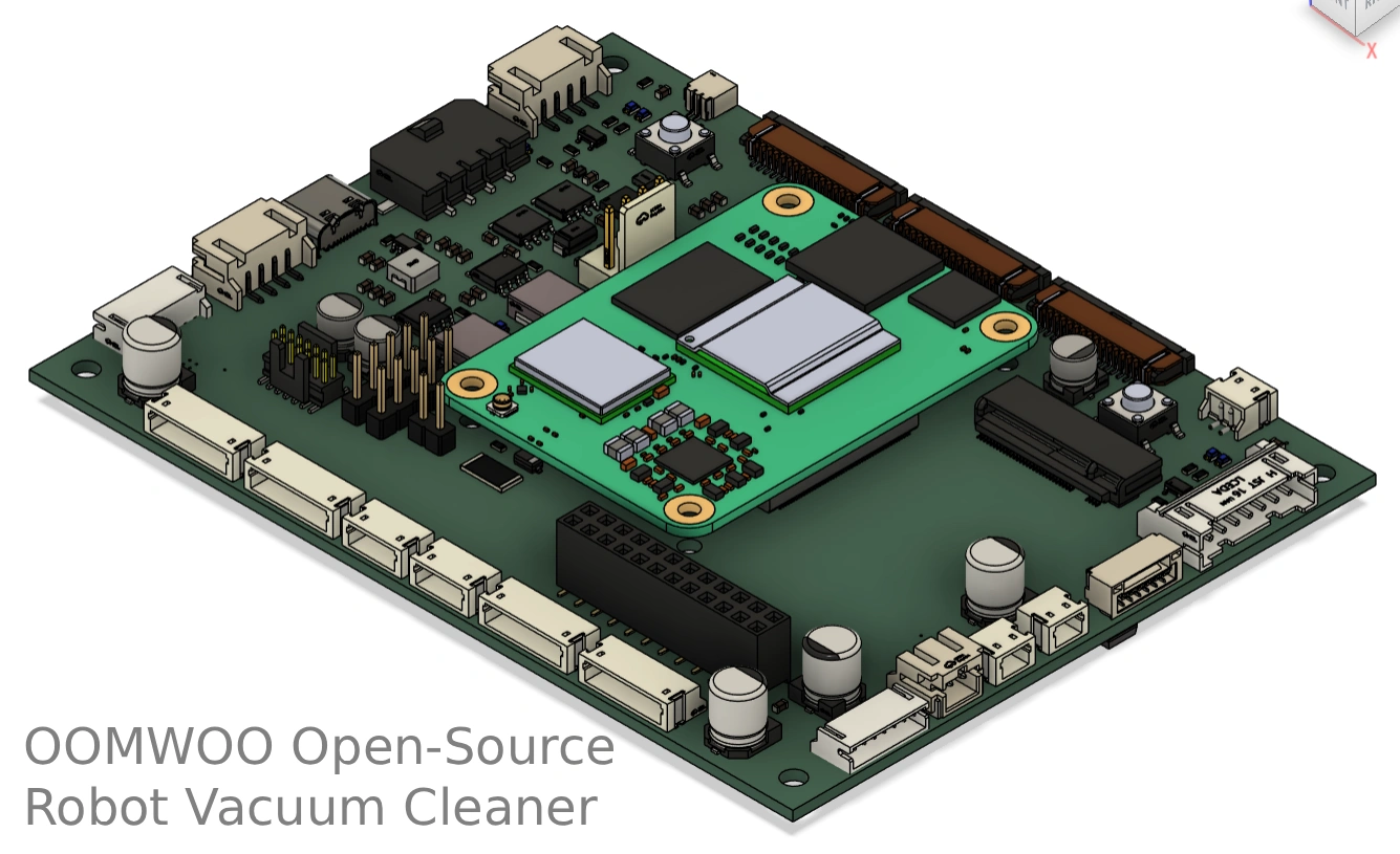
OOMWOO is our open-source robot vacuum that you build yourself. This post walks through its main circuit board module by module: what each part does, how we built it, and why we chose it. The board is still at the schematic stage. Layout comes next, so everything here can still change, and we would like your feedback before it does.
All the design files are KiCad, Apache-2.0, in the oomwoo-pcb repository. Parts, pinouts and measurements we collect along the way live in SPEC.md.
The big picture: two brains
Commercial robot vacuums split the work between an application processor and a microcontroller, and so do we. The processor thinks; the microcontroller keeps the robot safe and on time.
| Module | Its job | Main parts |
|---|---|---|
| Compute | Mapping, navigation, cameras, Wi-Fi, the app | Raspberry Pi Compute Module 5 (CM4 also supported) |
| Real-time controller | Motors, sensors, power switching, safety | STM32G473VCT6 |
| Power | Battery charging and all supply rails | SLM6900 charger, AP64501 bucks, MT3608 boost |
| Safety | Cuts actuator power if firmware hangs | RC charge-pump watchdog, gated rail switches |
| Motors | Wheels, brushes, fan, water pump | 4x DRV8870, fan and pump switches |
| Sensors | LiDAR, cliff, bumpers, carpet, IMU, docking IR | Connectors to sensor boards, ICM-42607-P |
| Audio | Voice prompts | NS4168 I2S amplifier |
Everything runs from a 4S lithium-ion pack (14.4 V nominal, 11.6 V empty, 16.8 V full). The motors take battery voltage directly, and the logic runs from regulated 5 V and 3.3 V.
Compute: a Raspberry Pi Compute Module carrier
The board is a carrier for a Raspberry Pi Compute Module. We picked a Compute Module over a full Pi because it is lower (the robot has to fit under furniture), a little cheaper, and many third-party modules share the pinout, including some with NPUs for camera-based obstacle detection.
- Two 15-pin MIPI camera connectors for the stereo cameras.
- An M.2 slot with its own 3.3 V buck that the Compute Module switches on, to experiment with AI accelerators.
- An SD card slot with a power switch.
- A Linux serial console on a 0.1-inch 5-pin header, so the single USB port stays free (see Debug and flashing).
- An internal USB header for the optional microphone board, with a 0.5 A polyfuse and ESD protection.
- I2S audio out to the speaker amplifier.
Real-time controller: STM32G473
The STM32G473VCT6 (LQFP-100) owns every motor, sensor and power switch. It talks to the Compute Module over a UART with a simple custom protocol, not micro-ROS, to keep third-party code out of the safety path.
Why this chip: it has enough pins, timers and ADCs for all the motors and sensors, plus built-in op-amps that amplify the carpet sensor echo without an extra part. It also has a USB device port and a real-time clock. An 8 MHz crystal clocks it, and a 32.768 kHz crystal and a small backup regulator keep the clock running, so the board needs no separate RTC chip.
Power: battery, charger and rails
The robot charges from 24 V, either from the dock contacts or from a barrel jack. The dock only switches its contacts on after it detects the robot. An SLM6900 buck charger, set up for 4S, charges the pack at about 2.2 to 2.6 A. The battery thermistor is wired straight into the charger, so over-temperature protection works in hardware even if the firmware does not.
| Rail | Made by | Feeds | Switched by |
|---|---|---|---|
| BAT-VCC (11.6 to 16.8 V) | Battery | Everything below | Power button latch |
| VCC-3V3 | AP64501 buck | STM32 | Power button (POWER-EN) |
| VCC-3V3-REG | From VCC-3V3 | Sensors, IMU, motor driver logic | STM32 |
| VCC-5V-REG | AP64501 buck | Compute Module, speaker, USB header | STM32 (5V_EN) |
| VCC3V3_M2 | AP64501 buck | M.2 slot | Compute Module |
| VUS (about 14.5 V) | MT3608 boost | Carpet sensor | Always on with 5 V |
| VM-VBAT | Battery via AO4407C | Wheels, brushes, fan | STM32 AND watchdog |
| VM-5V-LIDAR | 5 V via AO3401 | LiDAR, laser included | STM32 AND watchdog |
| VM-5V-WATER-PUMP | 5 V via AO3401 | Water pump | STM32 AND watchdog |
The carpet sensor gets its own boost rail because its echo amplitude tells carpet from hard floor. Running it from a battery that drifts between 11.6 and 16.8 V would make that comparison unreliable.
Safety: how the board fails safe
Our rule: if the firmware hangs, or the STM32 is being reset or reflashed, every motor, the pump and the LiDAR lose power. The board enforces this with passive parts and a few MOSFETs, and no watchdog chip.
The RC charge-pump watchdog
The STM32 toggles a pin (WDI) in software from its control loop. A capacitor passes only the edges of that signal to a P-channel MOSFET, and each edge tops up a hold capacitor. That capacitor voltage is WD_OK: about 2.7 V while the pin keeps toggling. If the pin sticks high, sticks low or floats, WD_OK falls below 1 V in about 100 ms. It also starts at 0 V at power-up, so nothing moves until the firmware is running.
- It must be toggled in software. A hardware timer or PWM would keep running after the CPU hangs.
- It uses only resistors, capacitors and a MOSFET that are already on the bill of materials.
Every actuator rail is WD_OK AND an enable pin
Each rail has a P-channel MOSFET switch. An N-channel MOSFET pulls its gate down only when WD_OK is high AND the STM32 drives its enable pin low. A 100k pull-up keeps each enable off while the STM32 is in reset or being flashed and its pins float. So the rail is on only while the firmware is alive and asks for it.
- The 14.4 V motor rail switches fast when it turns off, so a watchdog trip under full motor current does not cook the switch.
- The LiDAR rail soft-starts (about 1.5 ms) so it does not dip the 5 V that also powers the Compute Module. It cuts the whole LiDAR, not just its motor: a laser that keeps firing at one spot after its rotor stops is the unsafe case, whichever LiDAR you plug in.
- The pump rail has no soft start, so the pump can still be PWM-controlled.
Why we removed the watchdog chip
An earlier revision had an STWD100 watchdog that reset the STM32, plus an OR gate to disable it during debugging. Resetting the MCU does not by itself make the robot safe. Cutting actuator power does, and that is simpler. The STM32 still gets a reset path: its internal watchdog is forced on in hardware, and the Compute Module can pulse its reset line if the STM32 stops answering.
Motors and actuators
| Actuator | Driver | Connector | Notes |
|---|---|---|---|
| Drive wheels (x2) | DRV8870 each | JST ZH 7-pin | Hall encoder and wheel-drop switch in the same plug |
| Main brush | DRV8870 | JST ZH 2-pin | Up to about 7 A stall at 16.8 V (measured) |
| Side brush | DRV8870 | JST ZH 2-pin | |
| Suction fan | Fan has its own BLDC controller | JST PH 4-pin | Power, ground, PWM speed, FG tachometer |
| Water pump | AO3401 high-side switch | JST ZH 2-pin | 5 V peristaltic pump, current sensed by the STM32 |
Most motors are Roborock-compatible spares, so they are cheap and easy to find. SPEC.md has our bench measurements for each.
Sensors
- LiDAR: a JST GH socket for the LDROBOT LD14P, plus a 0.1-inch 4-pin header (RX, GND, MOT-, 5 V) for connecting other 2D LiDARs with jumper wires. The LiDAR sends its scans straight to the Compute Module over serial.
- Cliff and bumpers: a 16-pin JST PH connector compatible with iRobot Roomba 500 to 800 series sensor harnesses.
- Front sensor board: time-of-flight sensors, IR receivers for docking, and switched IR illumination for the cameras.
- Side sensor boards: side proximity and docking IR.
- Carpet sensor: a 290 kHz ultrasonic piezo facing the floor. One MOSFET with a 330 ohm pull-up drives short bursts, and the STM32 op-amp and ADC read the echo.
- IMU: an ICM-42607-P on the main board.
- Buttons and LEDs: power, clean and home buttons with status LEDs.
Docking IR uses 38 kHz receivers with the NEC protocol. We picked the Everlight IRM-H638T over the usual TSOP38238: it costs about a third as much and JLCPCB stocks it in depth.
Audio and microphones
An NS4168 class-D amplifier takes I2S straight from the Compute Module and drives the speaker. It is a MAX98357A equivalent at about half the price, and in an ESOP-8 package you can solder by hand. It needs no master clock (the Pi cannot output one) and works with the standard Raspberry Pi max98357a overlay on both CM4 and CM5.
Microphones are not on the main board. For people who want voice control, we plan an optional mic-array board on top of the LiDAR cage: four PDM MEMS microphones and an RP2040 that shows up as a standard 4-channel USB microphone. It plugs into the internal USB header.
Debug and flashing
- Compute Module console: a 0.1-inch 5-pin UART header that fits common 3.3 V USB-serial cables.
- STM32: a 1.27 mm 2×7 STDC14 header for an ST-LINK V3 MINIE, plus a 0.1-inch UART header.
- Normal firmware updates need no probe: the Compute Module reflashes the STM32 itself, over the STM32 serial bootloader or over SWD from its own GPIOs.
- Flashing the Compute Module eMMC uses the internal USB header and a boot jumper.
How we pick parts
- Hand-solderable packages (SOIC, ESOP) over QFN wherever the cost is similar, so the board stays hackable and repairable.
- Fewer different parts. For example, we cut the MOSFETs from eight part numbers to four: AO3400 and AO3401 for small switches, AO4407C for battery-side switches, and AOD407 only where the 24 V charger input needs 60 V.
- Check the datasheet for gate-source voltage. Small SOT-23 MOSFETs are often rated only 12 V, and a gate pulled from 16.8 V to ground would destroy them.
- Deep stock at JLCPCB. We plan to build in batches of hundreds, so unit price and stock depth matter more than whether a part is a JLCPCB “Basic” part.
Parametric search on part sites is patchy, so we export whole part categories from JLCPCB, with stock, price and parameters, and filter them ourselves.
What schematic review caught
Building in public means showing the mistakes too. These are the problems we have found and fixed in the schematic so far:
- A rotated logic chip put its ground pin on the same wire as its supply pin, shorting 3.3 V to ground.
- The LiDAR motor MOSFET had its drain wired to ground, so it could not switch anything.
- Several small MOSFETs rated 20 V sat on nodes that see the full 16.8 V battery.
- The carpet driver was a P/N half-bridge whose high side turned off through a 100k resistor: far too slow at 290 kHz, so both transistors would conduct at once each cycle.
- The carpet sensor supply was set to 20 V instead of the intended 14.4 V.
Open questions and next steps
- Layout: our PCB engineer has done preliminary placement. PCB shape will be informed by the mechanical design.
- The USB-C port for the phone-as-compute option needs its CC pins configured, so phones recognise it both for charging and as a USB device.
- We are asking the carpet sensor vendor for its reference driver circuit, to confirm drive voltage and pull-up value.
- We still need to measure the suction fan controller’s input capacitance, which sets the inrush on the motor rail.
- Firmware: the watchdog toggle, active-low enables, carpet bursts, and the STM32 internal watchdog settings.
Want to help or spot a problem? Open an issue on GitHub or join us on Discord.