Tutorial: Connect 3irobotix Delta-2A LiDAR to Raspberry Pi (Python)
Read distance data from a 3irobotix Delta-2A on a Raspberry Pi in Python — and run the PID + PWM loop that spins its motor at 6 Hz via the Maker's Pet driver board, no ESP32 required.

The 3irobotix Delta-2A is another inexpensive 2D LiDAR you can drive straight from a Raspberry Pi. Like the Xiaomi LDS02RR, it has no onboard motor controller — you keep it spinning at the right speed. The difference is the adapter: instead of a small breakout, this guide uses the Maker’s Pet ESP32 driver board, which has the same motor-driver circuit built in. No ESP32 needs to be plugged in — the Pi does everything.
All functionality in this article is now available as a Python
lds2dlibrary.
The trick: the Delta-2A must turn at about 6 Hz to keep streaming. The driver board’s
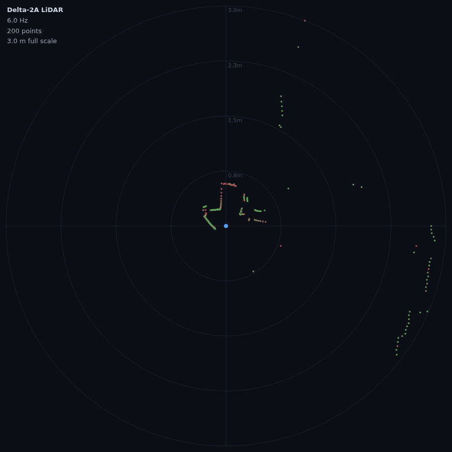
MOT_ENinput switches the motor; the Pi drives it with a PWM signal and runs a PID loop that reads the speed the Delta reports and trims that PWM to hold 6 Hz. The packet format and PID constants are ported from the open-source kaiaai/LDS library. Tested on a Raspberry Pi 5 (software PWM on GPIO18): the PID locks the Delta-2A at ~6 Hz and streams clean data. Bug reports welcome on our support forum.
Why the Delta-2A needs the host to spin it
Some LiDARs hold their own speed; the Delta-2A does not. Its motor only runs while a MOT_EN line is driven, and the rotation speed follows the PWM duty cycle on that line. There is no “set 6 Hz” command — closing that loop in software is the interesting part of this build, and it is the same idea we used for the LDS02RR.
Already wired a Delta to an ESP32? That is the companion Arduino guide; here we move to a Raspberry Pi 5 and Python.
What you need
- 3irobotix Delta-2A LiDAR
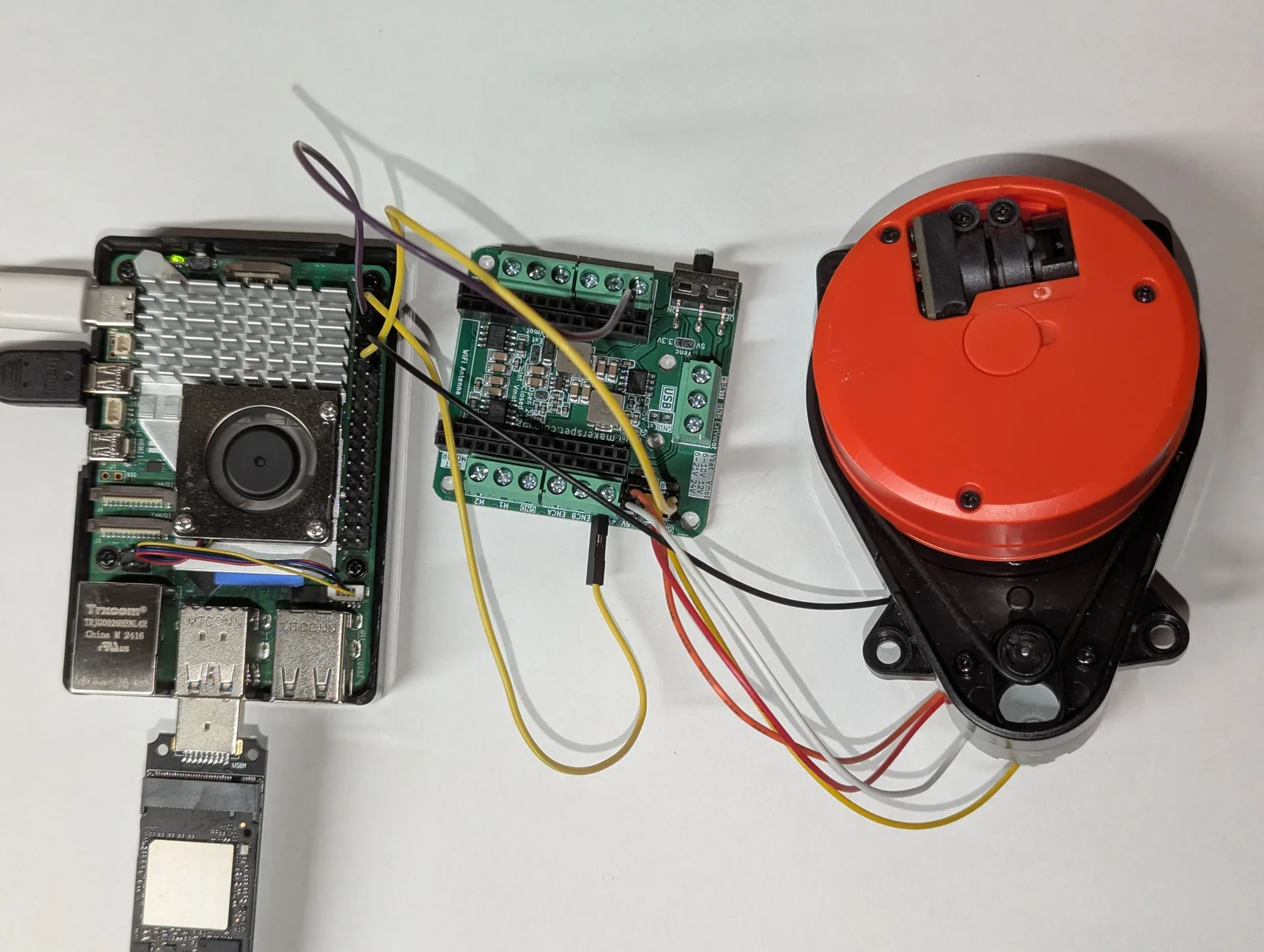
- Maker’s Pet ESP32 driver board — it carries a 30-pin ESP32, but for this experiment we leave the ESP32 out and use only its built-in LiDAR motor-driver circuit
- A Raspberry Pi 4 or Pi 5 on Raspberry Pi OS (Bookworm or newer)
- A strong 5V Pi power supply — the LiDAR motor pulls up to ~1A peak
Get new tutorials by email
Wiring
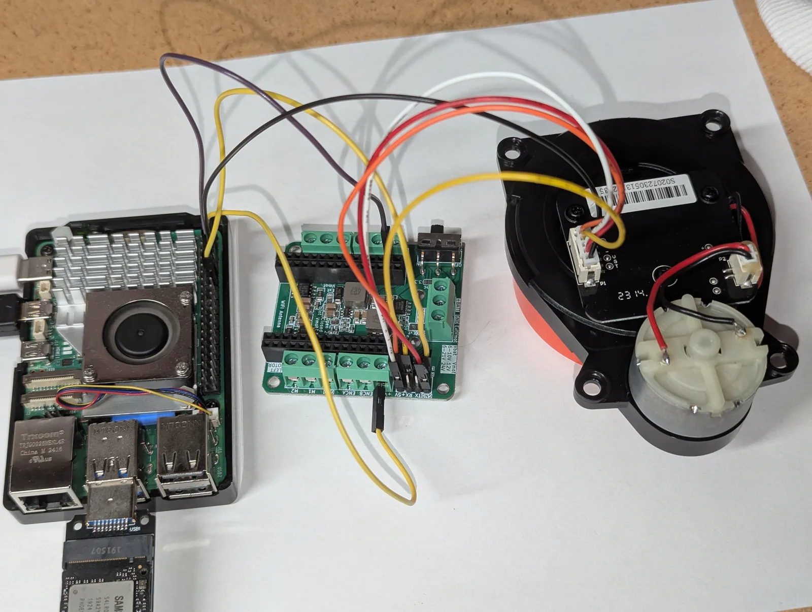
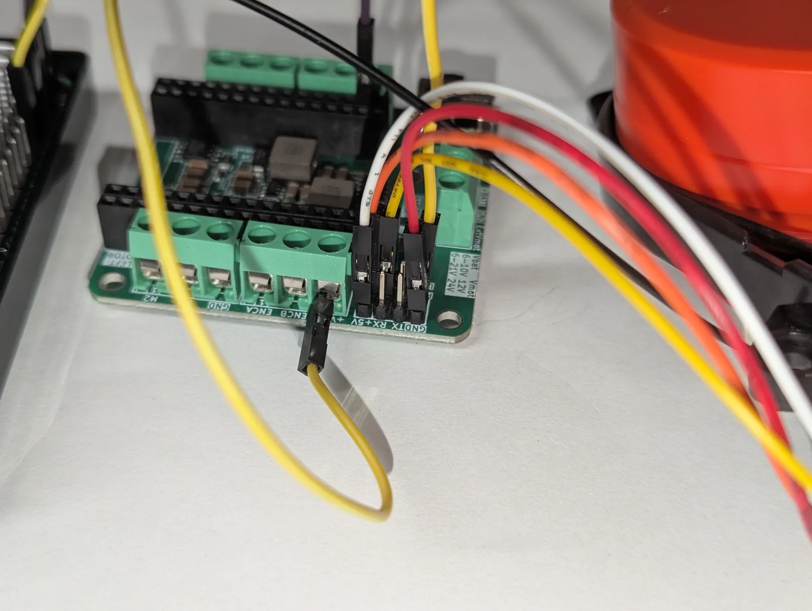
The Delta-2A plugs into the board’s LiDAR connector. Four wires run from the board to the Pi — the Pi drives the motor and listens to the LiDAR:
| Board signal | Delta-2A | Pi Header Pin | Purpose |
|---|---|---|---|
| PWM | Pin 12 (GPIO18) | Motor PWM out (3.3V, several kHz) | |
| TX | Pin 10 (GPIO15 / RXD) | LiDAR data in (3.3V, read-only) | |
| 5V | 5 V | Pin 2 or 4 | LiDAR power (~1A peak) |
| GND | GND | Pin 6 | Common ground |
| M- | MOT- | LiDAR DC motor negative | |
| 5V | MOT+ | LiDAR DC motor positive |
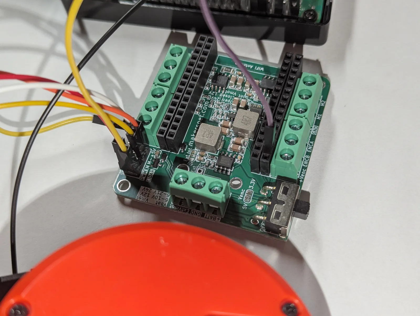
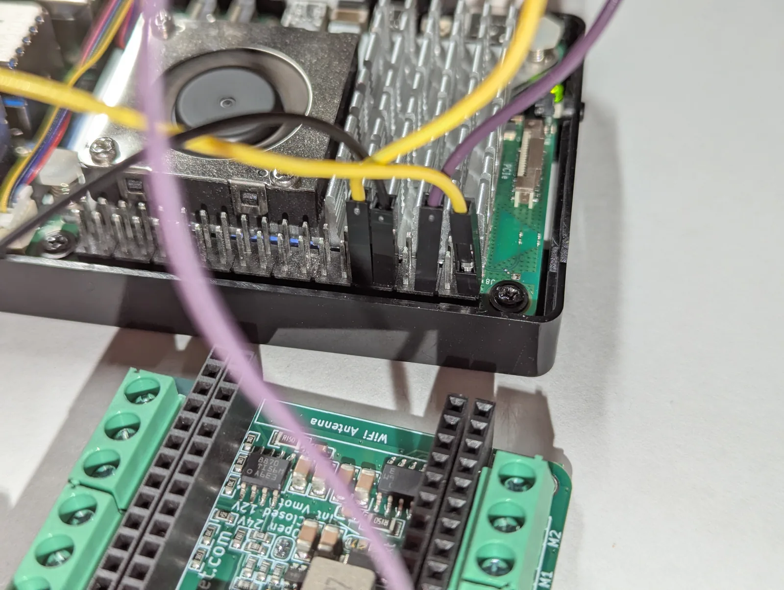
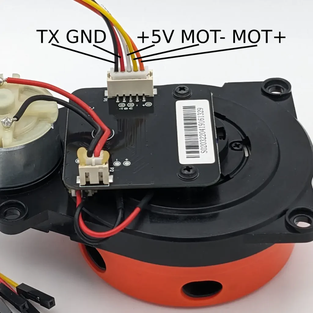
3.3V logic throughout, so no level shifter is needed.
One-time Raspberry Pi setup
Serial port: enable the GPIO UART and free it from the serial console exactly as in the LD14P guide — identical steps. The Delta-2A runs at 115200 baud; some units are 230400 (use --baud 230400).
Pick how to drive MOT_EN (the code supports both via a --pwm flag):
- Software PWM (default, tested) — any GPIO via
gpiozero, no config change. Verified on a Raspberry Pi 5 holding the Delta-2A at 6 Hz on GPIO18 (header pin 12). - Hardware PWM (not yet tested) — cleaner multi-kHz; add
dtoverlay=pwm-2chanto/boot/firmware/config.txtand reboot (the Pi 5 may need--pwm-chip 2). Supported in the code but not yet verified on hardware.
# pyserial for the data, gpiozero + rpi-hardware-pwm for the motor PWM
sudo apt install python3-serial
pip install gpiozero rpi-hardware-pwmHow the speed-control loop works
Every Delta packet carries the current scan frequency (the speed byte divided by 20 gives Hz). That is the feedback signal: a PID compares it to the 6 Hz setpoint and nudges the MOT_EN duty up or down. The PID output range is simply 0.0 to 1.0 — the duty cycle itself:
# 6 Hz target. The PID's output IS the MOT_EN duty cycle (0.0 - 1.0).
pid = PID(kp=0.3, ki=0.1, kd=0.0, setpoint=6.0,
          out_min=0.0, out_max=1.0, sample_ms=20)
pid.initialize(current_input=0.0, current_output=0.6)
pwm.set_duty(0.6)                        # start MOT_EN at 60%

while True:
    for scan_freq_hz, points in read_packets(serial):
        measured_hz = scan_freq_hz       # the Delta reports its own speed
    duty = pid.compute(measured_hz)      # runs every 20 ms
    if duty is not None:
        pwm.set_duty(duty)               # trim MOT_EN to hold 6 Hz
At startup the motor is stationary and sends nothing, so the controller ramps the duty up until the Delta reaches speed and packets start arriving; then it settles onto 6 Hz.
How LiDARs are used in self-driving robots?
Build a real LiDAR self-driving Arduino/ROS2 robot using our kit - with complete step-by-step instructions. No robotics experience necessary.
See the full robot kit →Reading the Delta packets
The Delta-2A uses the 3irobotix format: packets start with 0xAA, carry a length, the scan speed, a start angle, and a run of (quality, distance) samples, ending in a checksum. Multi-byte fields are big-endian, distances are in quarter-millimetres, and 16 packets make one full 360° scan.
START = 0xAA          # 16 packets make one 360-degree scan; fields are big-endian
def parse_packet(pkt):
    scan_freq_hz = pkt[8] * 0.05         # motor speed, fed back to the PID
    start_angle  = u16(pkt, 11) * 0.01   # this packet's first angle, degrees
    ...                                  # then N x (quality, distance/4 mm)
The full parser, PID, and PWM back ends are in one readable file, delta_2a_pi.py.
Run it
# software PWM on GPIO18 (header pin 12), summarized output
python3 delta_2a_pi.py

# one line per measurement point
python3 delta_2a_pi.py --raw

# watch only the spin-up and speed lock (handy for tuning)
python3 delta_2a_pi.py --spin

# some Delta-2A units run at 230400 baud
python3 delta_2a_pi.py --baud 230400
Power up, start the script, and watch the spin-up: the duty climbs, the Delta comes up to speed, and once it is near 6 Hz the distance lines start scrolling. --spin shows just the live frequency and duty so you can confirm the loop locks. The motor stops automatically on Ctrl-C.
If it will not hold speed
- Make sure your 5V supply has headroom — a sagging rail starves the motor.
- No data at all? Try
--baud 230400; some Delta-2A units ship at the higher baud. - Prefer hardware PWM if software PWM jitter disturbs the loop.
- Re-tune with
--kp,--ki,--kdwhile watching--spin.
Where this is going
With the Delta-2A holding 6 Hz and streaming clean distances, it feeds the same pipeline as every other LiDAR in this series: a live browser radar, obstacle detection, and — published as a ROS 2 LaserScan — SLAM and Nav2 mapping.
Parts used here: the 3irobotix Delta-2A and the ESP32 driver board. All the code is in the rpi5_delta_2a repository under the Apache 2.0 license.