OOMWOO hardware bring-up: wheels, fans and brushes

OOMWOO is built from sourced vacuum parts – Roborock drive wheels, off-the-shelf blower fans, iRobot cliff sensors. Before the I/O board can be laid out, each part has to be brought up on the bench: identify the connector, work out the pinout, and measure what it actually draws. This post collects those results as they land.
Drive wheels
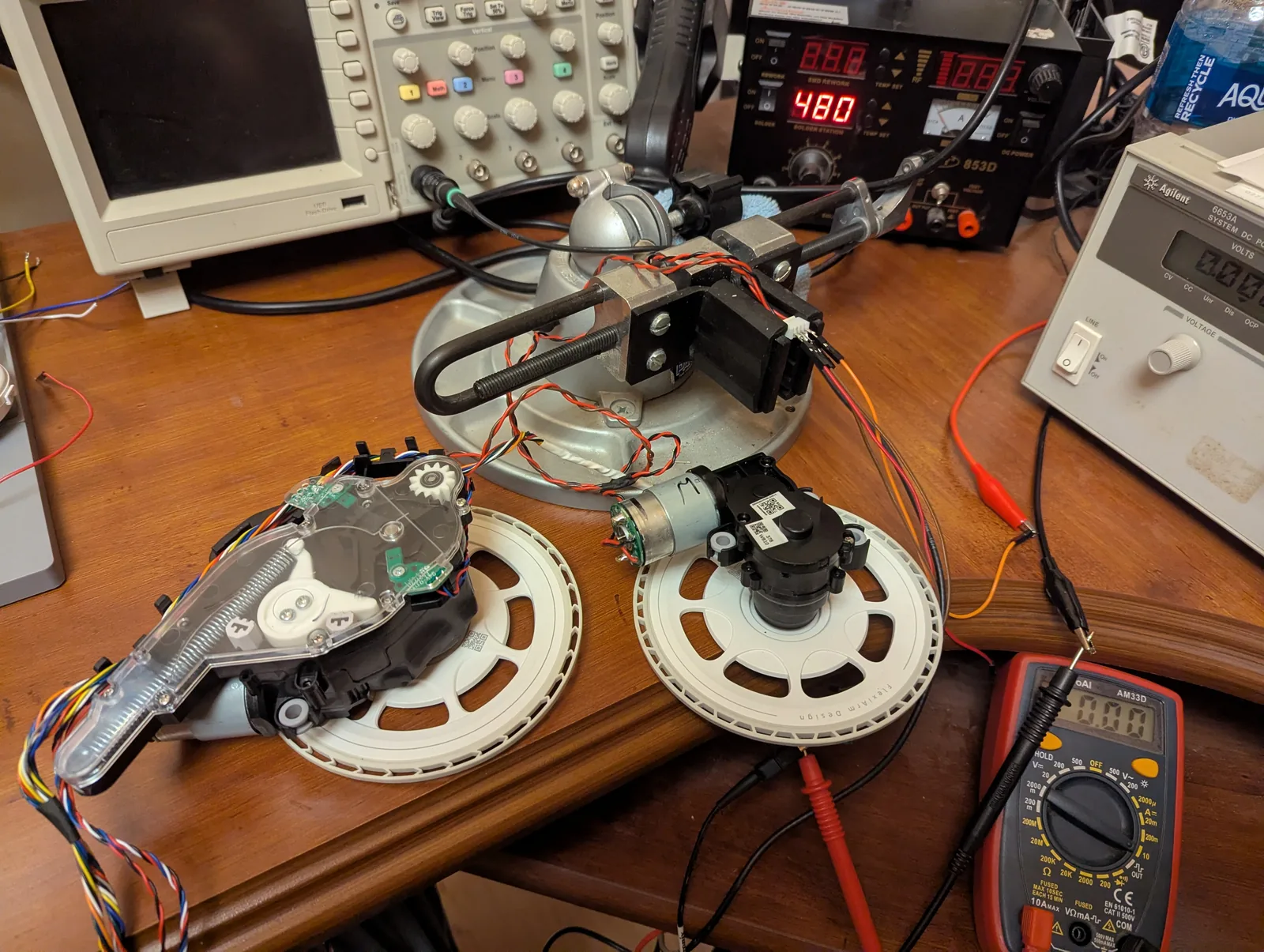
The drive wheel is a Roborock S5 Max assembly – motor, gearbox, Hall encoder and a wheel-drop switch in one unit. Driving the motor at 15V or less and watching the encoder output confirms the pinout: pulse frequency is proportional to wheel speed.
Roborock S5 Max wheel assembly
connector  JST ZH 1.5mm 7-pin male (board side female)
current    0.14A no load, 1.7A stall at 14.4V

pin 7  wheel-drop switch, on
pin 6  wheel-drop switch, common
pin 5  Hall Vcc 3.3-5V     (orange)
pin 4  Hall OUT, open collector (blue)
pin 3  Hall GND            (brown)
pin 2  MOT-
pin 1  MOT+
Suction fans
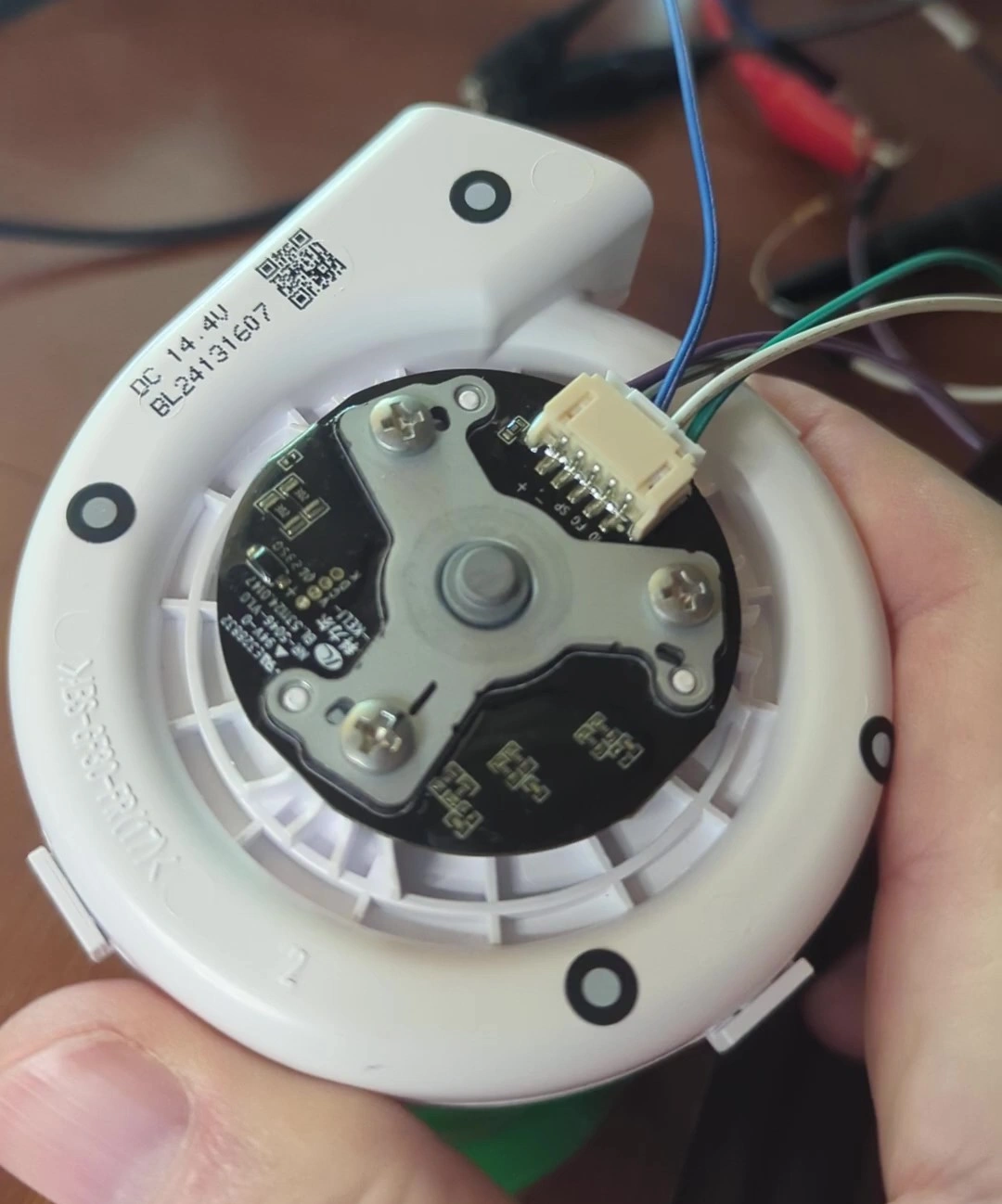
The blower is the other big load. The BL24131607 runs straight off the 4S pack, takes a PWM input and reports back a tacho signal.

BL24131607 suction fan, DC 14.4V
connector  JST PH 2.0mm 5-pin female
current    1.7A free, 2.7A with the intake blocked, at 15V

pin 5  + (VMOT)
pin 4  - (GND)
pin 3  SP (PWM)
pin 2  FG (tacho)
pin 1  ID (20K pulldown to GND, likely fan-presence detect)
Four more fans – 20N704R990F, MSD-C-3, MSD-D and 20N709U020 – share a single 4-pin pinout, which makes them drop-in alternatives:
20N704R990F / MSD-C-3 / MSD-D / 20N709U020, DC 14.4-15V
connector  JST PH 2.0mm 4-pin female

pin 4  VMOT
pin 3  GND
pin 2  PWM, low = off
pin 1  TACH, open collector
Others use different housings: 22N704V160 and BL24131616 on JST PA 2mm 5-pin, BL27302101 on JST PA 2mm 6-pin, MSD-G-V1 on Molex Micro-Fit 3.0. Pinouts for these are in the spec.
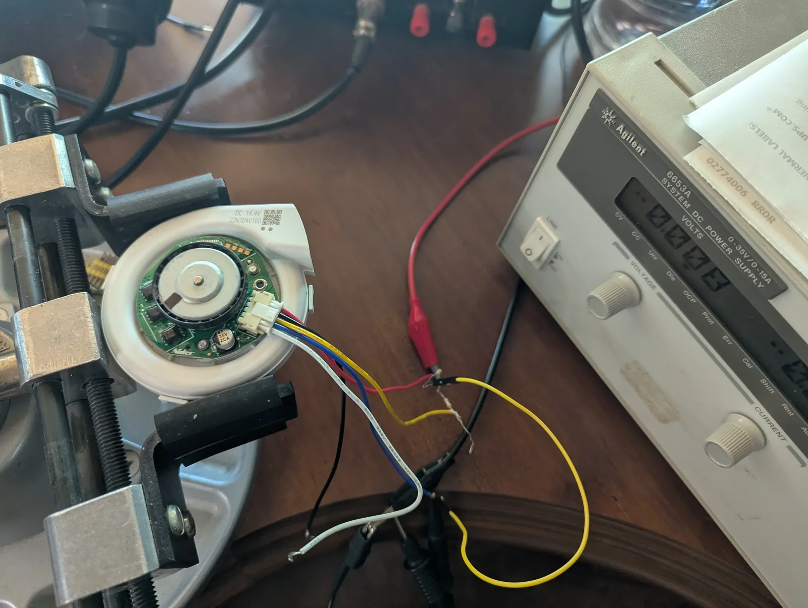
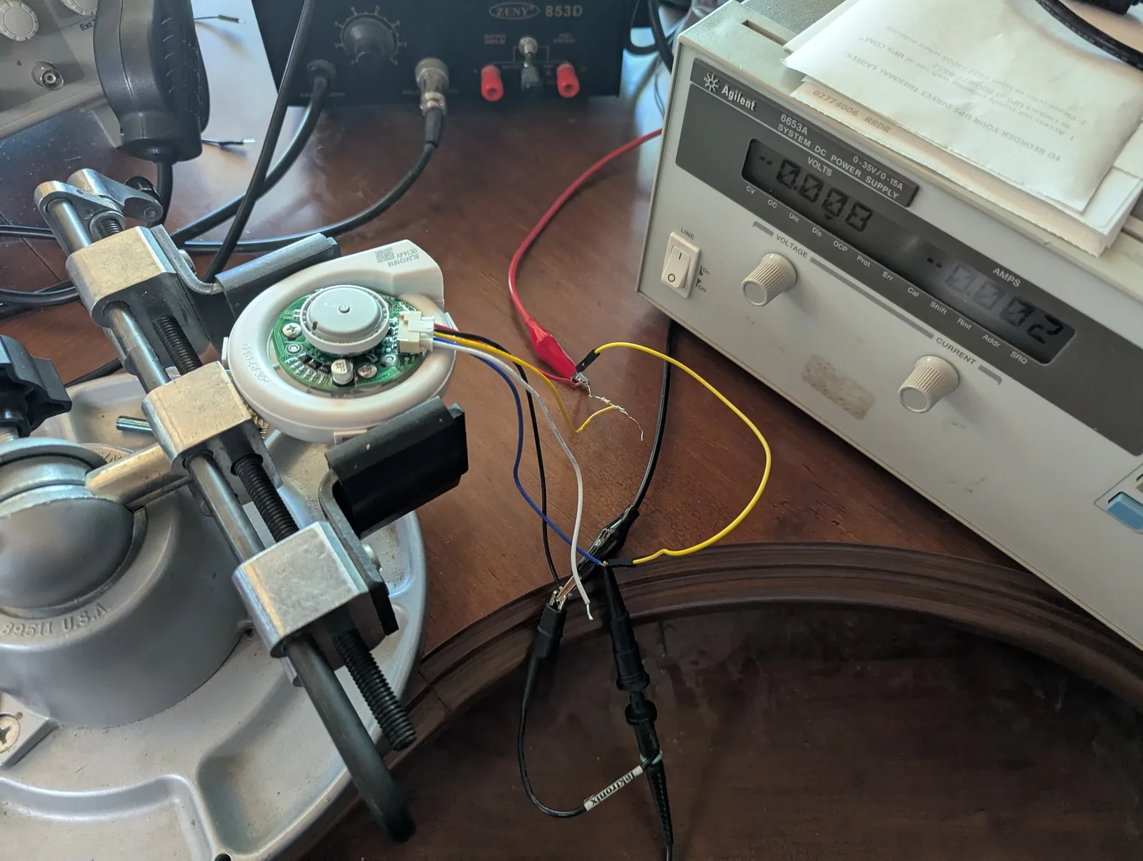
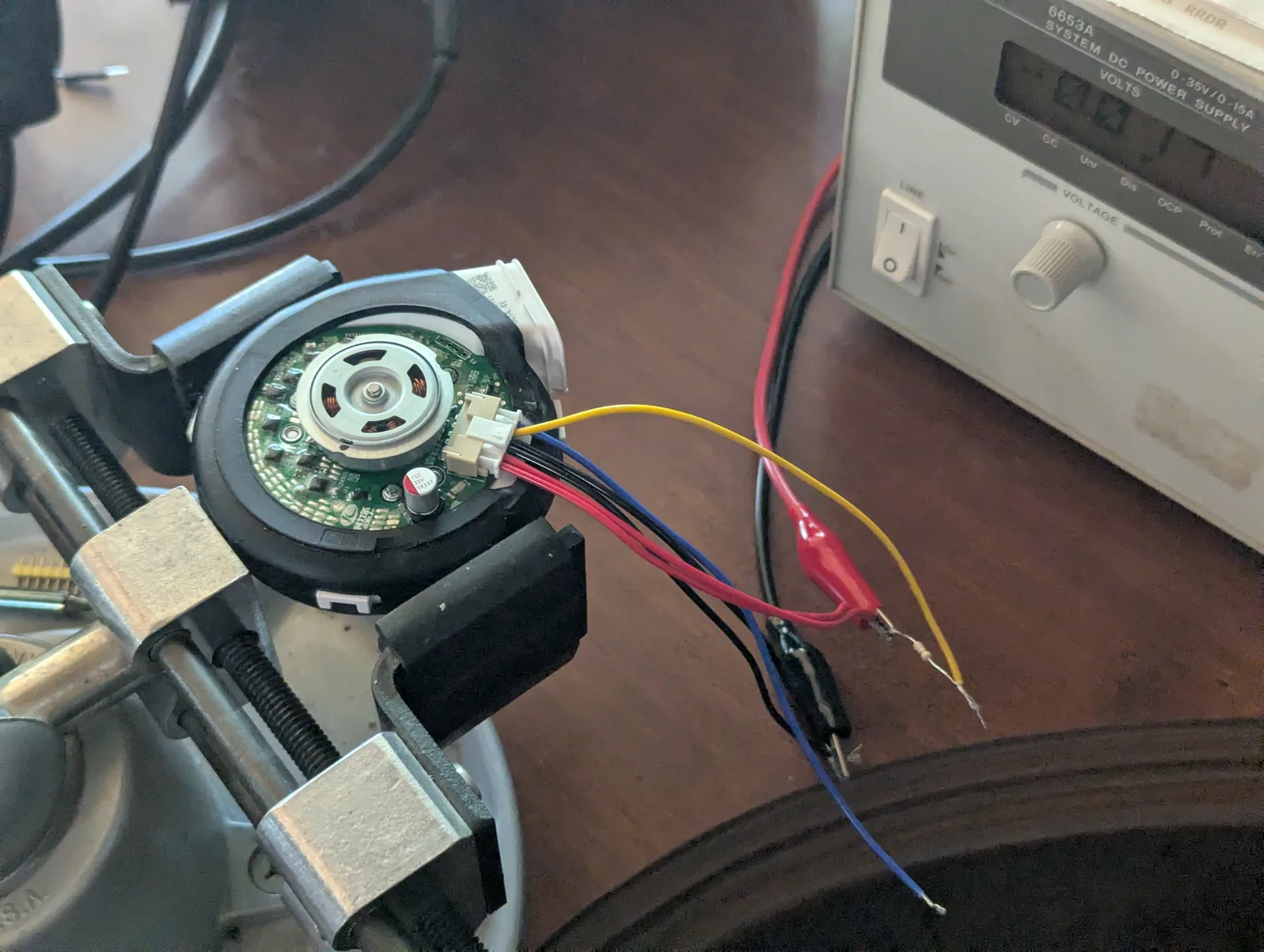
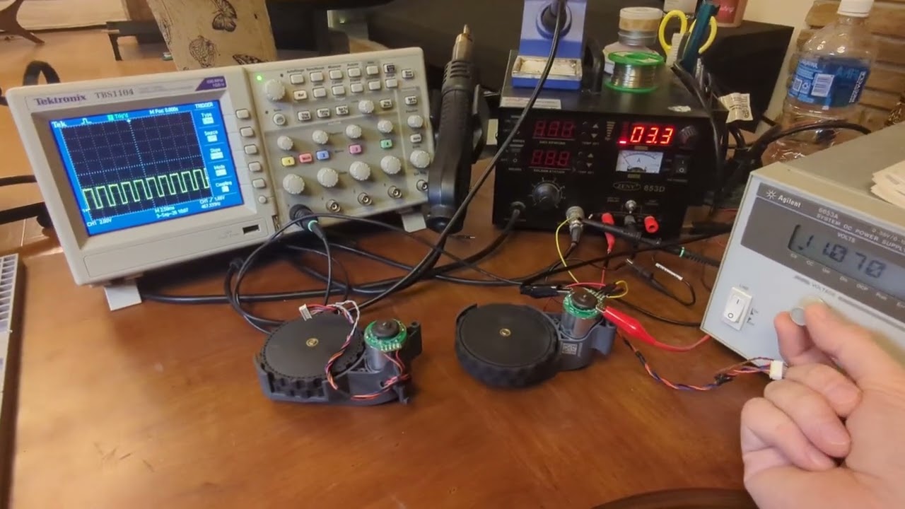
The MSD-G v1 is the outlier. At roughly 20 kPa it is about three times the suction of the BL24131607, and it bills for it: 3.65A unloaded at 16.8V and 6A against a blocked intake. That is a different driver class from the ~2A fans above, so which fan OOMWOO ships is a PCB decision, not just a performance one.
One measurement worth flagging: its unloaded current goes up as the pack drains – 3.65A at 16.8V, 4.2A at 14.4V, 5.25A at 12V. The controller is holding roughly constant power, so the worst case for the wiring, the connector and the FET is a flat battery, not a full one. Sizing off the 16.8V figure would under-spec the whole path by about 40%.

Testing the whole batch turned up something that makes the table worth more than the sum of its rows: the fans do not agree with each other. Some hold power roughly constant, so current climbs as the pack drains. Some just draw more as they load up. At least one draws less. There is no house style to lean on, which means a candidate fan has to be swept across the voltage range, free and blocked, before it can be designed around. Picking a driver off one number at one voltage is how you find out the hard way.
Main brush
The main brush motor from a Roborock S50/S51/S55 or XIAOWA C10 measures 0.26A no load and 3.5A stall at 14.4V.
Side brush
An extendable side brush off a Dreame is the neatest piece of engineering in the batch. It reaches out past the body to sweep a corner, then folds back in – and it does both with one motor. Spin it one way and the brush sweeps; spin it the other and the arm drives in or out. An IR proximity sensor on the little PCB up top reports whether the arm is folded out or in.
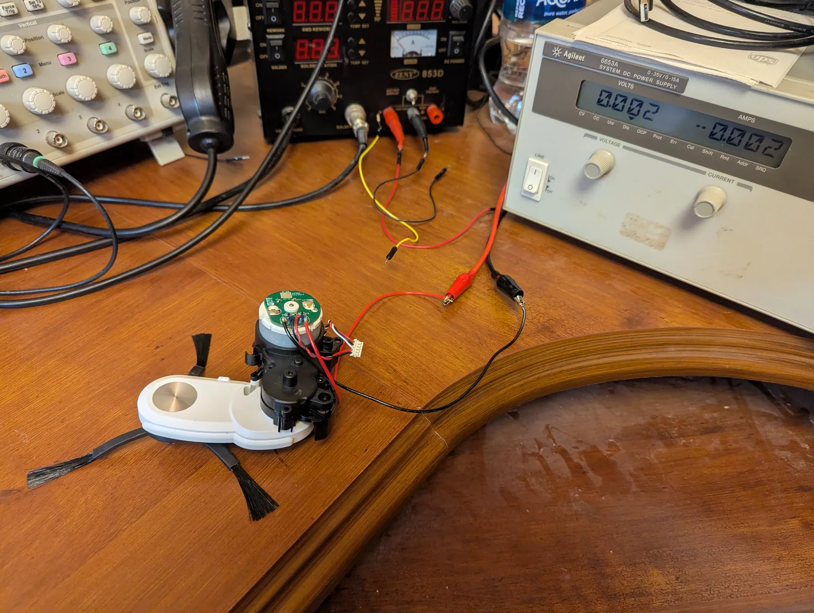
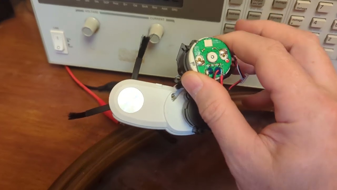
One motor is cheap and compact, but it costs you a degree of freedom: sweep direction and arm position are the same command. The robot cannot hold the arm out and reverse the brush, so extend and retract have to be scheduled around cleaning rather than commanded freely. Worth knowing before the software assumes otherwise.
Cliff sensors
The iRobot cliff sensor loom lands on a JST PAD 2.0mm 8×2 housing, mating JST S16B-PHDSS or B16B-PADSS on the board.
Why measure
Salvaged vacuum parts mostly come without datasheets, so the spec started out with rough estimates. Measured numbers replace them, and they are what sizes the H-bridges and load switches, the wire gauge and the battery budget. An afternoon on the bench is a lot cheaper than a board respin.
Mechanical assemblies
Alongside the electrical bring-up, the mechanical side is being reverse-engineered into CAD. These assemblies exist now, though none are optimized for 3D printing yet – splitting them for build volume and cutting supports is the next pass.
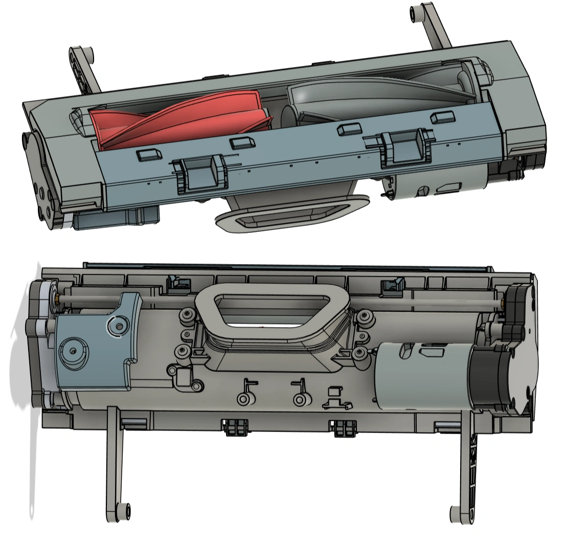
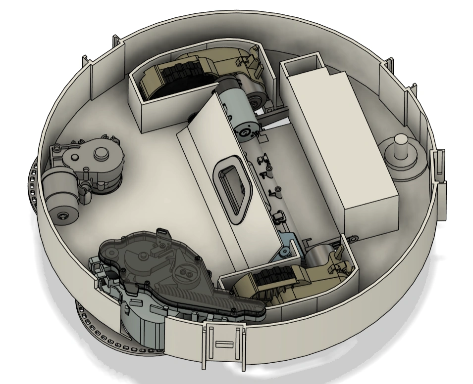
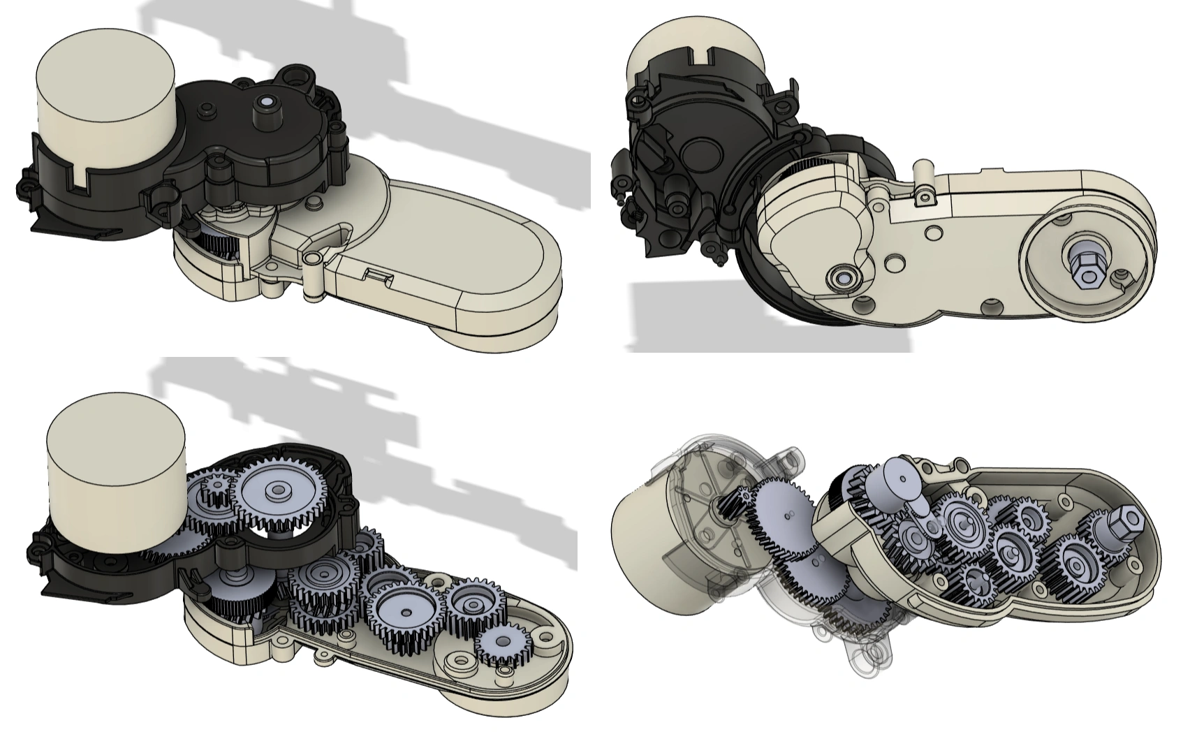
How these get made – sourcing, 3D scanning and the CAD pipeline – is covered in how the 3D design gets made.
Where this lives
Every pinout, connector part number and measurement goes into docs/SPEC.md in the oomwoo-pcb repo, which is what the schematic is drawn against. If you own one of these parts, a measured current or a confirmed pinout is a genuinely useful contribution – see the RFC board, particularly part-specs and io-pcb.
Related: how to source the BOM for the parts these numbers describe, and the build instructions as assemblies land.
Follow OOMWOO build
Open-source robot vacuum community build updates
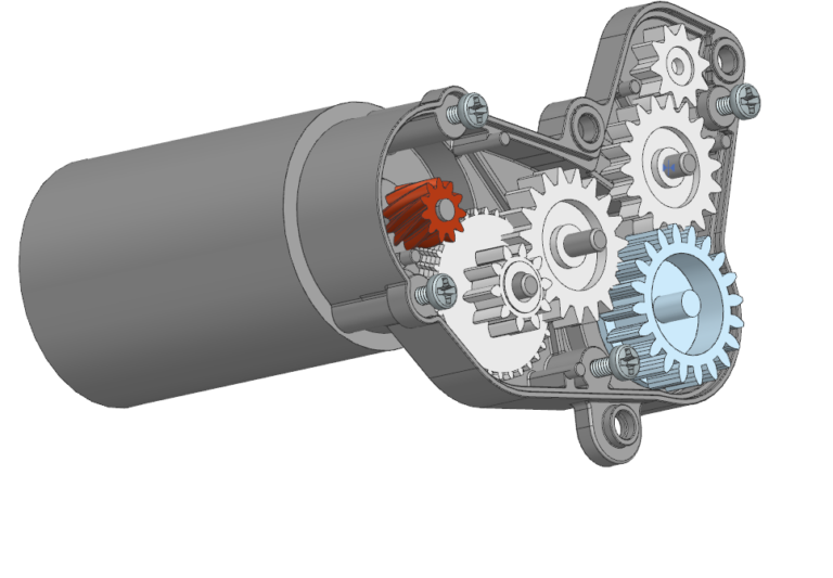
[…] hardware bring-up covers what happens once these parts are on the bench – pinouts, connectors and measured […]
[…] sourced motors, fans and sensors – connectors, pinouts and measured currents – are in hardware bring-up, and the CAD pipeline behind these parts is in how the 3D design gets […]